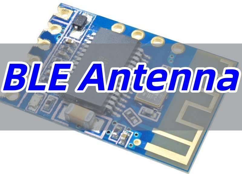
BLE antenna is a critical component responsible for transmitting and receiving the 2.4 GHz radio signals that enable Bluetooth Low Energy (BLE) communication. This article provides a comprehensive guide to BLE antennas, covering their definitions, types, design rules, and how they ensure robust connectivity in modern electronics.
Do you struggle with unreliable wireless performance in your BLE devices? Many engineers and product developers face significant challenges when integrating a BLE antenna.
- Inconsistent Range: Performance varies dramatically based on device placement and environment.
- Signal Interference: Susceptibility to noise from other 2.4 GHz devices like Wi-Fi routers.
- Complex PCB Integration: Difficulty in designing an effective PCB Bluetooth antenna, especially on space-constrained boards.
- Poor Radiation Efficiency: Inadequate antenna design leads to high power consumption, defeating the “low energy” advantage of BLE.
- Costly Prototyping Cycles: The need for multiple revisions to fix antenna-related issues drains time and budget.
Fortunately, these challenges can be systematically overcome with proper expertise. The solutions often lie in:
- Optimal Antenna Selection: Choosing the right type, whether a BLE chip antenna for miniaturization or an external antenna for maximum range.
- Precision RF Layout: Adhering to strict BLE PCB antenna design rules for impedance control and ground plane management.
- Advanced Signal Processing: Implementing techniques like antenna diversity to combat signal fading in software.
- Rigorous Performance Validation: Using OTA testing and VSWR measurements to verify performance before production.
- Expert Manufacturing Partnership: Working with experienced PCB manufacturers who understand RF material selection and design for manufacturability.
At BEST Technology, we are a professional PCB and RF solution provider with deep expertise in BLE antenna design and integration. We help our clients navigate these complexities to achieve optimal wireless performance, ensuring their products are reliable and market-ready. Pls feel free to contact us at sales@bestpcbs.com to discuss your project.
What Is a BLE Antenna?
A BLE antenna serves as the fundamental interface that converts electrical signals from a Bluetooth Low Energy chip into electromagnetic waves for wireless transmission, and vice versa for reception. Understanding its basic definition and the technology it supports is crucial for anyone working with BLE devices.
A BLE antenna is a transducer specifically designed to radiate and capture electromagnetic waves in the 2.4-2.485 GHz ISM band, which is used for Bluetooth Low Energy communication. The core BLE antenna definition revolves around its role as the essential interface between the BLE chip’s electrical signals and free-space radio waves.
To understand the BLE antenna meaning fully, it’s important to answer a few key questions:
- What is BLE wireless? Bluetooth Low Energy (BLE) is a low-power, short-range wireless communication protocol designed for applications that need to exchange small amounts of data periodically rather than sustain a continuous, high-throughput data stream.
- Is BLE a tracking device? BLE itself is not a tracking device; it is a communication protocol.
However, its ultra-low power characteristics make it the ideal technology for building battery-operated tracking tags and beacons. - Is BLE faster than Wi-Fi? No, BLE is significantly slower than Wi-Fi.
The trade-off is power consumption; BLE uses a fraction of the energy, enabling devices to run for months or years on a small battery.
In summary, a BLE antenna is specifically optimized for the power-efficient, short-range communication requirements of Bluetooth Low Energy technology. Its design fundamentally differs from antennas used for higher-speed protocols like Wi-Fi, prioritizing low power consumption and miniaturization over raw data throughput.
What Is a BLE Antenna Array?
While a single antenna element suffices for basic communication, a BLE antenna array represents an advanced approach that uses multiple antenna elements to enable sophisticated functionality like precise location tracking and improved signal reliability.
A standard BLE antenna uses a single element. A BLE antenna array, however, consists of multiple antenna elements working together. This configuration enables advanced radio functionalities that are impossible with a single antenna. A prominent application is the BLE AoA (Angle of Arrival) antenna array, which uses the precise phase differences of a signal as it arrives at each element in the array to calculate the direction of the transmitting device.
Applications of BLE AoA Antenna Array:
- Factory Asset Management: Track tools, equipment, and inventory in real-time with high accuracy within a large facility.
- AGV Navigation: Provide centimeter-level positioning to guide Autonomous Guided Vehicles (AGVs) reliably through dynamic environments.
- Smart Warehousing: Enable precise indoor localization of goods, drastically reducing search times and optimizing storage layout.
The BLE antenna array significantly expands the capabilities of Bluetooth technology beyond simple data transfer, enabling precise spatial awareness that is revolutionizing industrial automation, logistics, and asset tracking applications where location intelligence is critical.
What Are the Types of BLE Antennas?
Selecting the appropriate antenna type is one of the most critical decisions in BLE product development. The choice involves balancing factors like performance, size, cost, and integration complexity, with options ranging from fully integrated to external solutions.
BLE antennas are primarily categorized into integrated and external types, each suited for different applications.
Integrated Antennas (on the PCB):
- PCB Trace Antenna: A conductive trace etched directly onto the PCB, offering a very low-cost solution.
- Chip Antenna: A tiny surface-mount device (SMD), ideal for extremely space-constrained products.
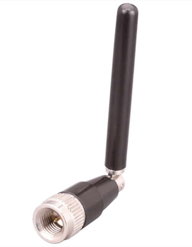
External BLE Antenna Types (connected via a cable/connector):
- Magnetic Base Antenna: An external antenna with a magnetic base for easy temporary attachment to metal surfaces, useful for testing or fixed stations.
- Rubber Duck Antenna: A common omnidirectional rubber-coated rod antenna, providing good all-around coverage and durability.
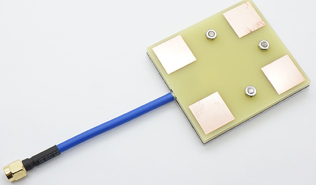
- Patch Antenna: A flat, directional antenna typically mounted on a surface, used when signals need to be focused in a specific direction.
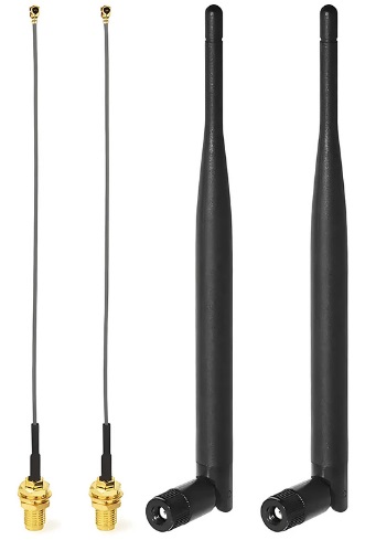
- IPEX/U.FL External Antenna: This refers to any external antenna (like a rubber duck or patch) that connects to the PCB via a small IPEX (U.FL) connector, providing flexibility and optimal placement.
The diversity of BLE antenna types allows designers to select the optimal solution for their specific application requirements, whether prioritizing miniaturization with chip antennas or maximizing range and performance with external antennas. Understanding these options is essential for making informed design decisions.
What Are the Best Scenarios to Use a BLE Chip Antenna?
The BLE chip antenna represents a popular choice for modern compact electronics, but its advantages are particularly pronounced in specific applications where size constraints are paramount.
The BLE chip antenna is the preferred choice when minimizing the physical size of the product is the highest priority. Its small form factor makes it ideal for:
- Ultra-Compact Devices: Such as mini sensors or tags where every cubic millimeter counts.
- Wearable Devices: Including smart rings, fitness bands, and small smartwatches that must be lightweight and unobtrusive.
- Beacons: Small, battery-powered devices used for proximity marketing or indoor positioning that are often discreetly placed.
- Smartbands/Handsets: Devices worn on the wrist that require a compact and reliable integrated antenna solution.
In applications where miniaturization is non-negotiable, the BLE chip antenna provides an excellent balance of size, performance, and integration ease. However, designers must carefully consider its dependency on a proper ground plane and PCB layout to achieve optimal performance.
What Are the BLE PCB Antenna Design Rules?
Designing an effective PCB trace antenna for BLE requires strict adherence to RF principles that govern how efficiently electrical energy is converted into electromagnetic radiation.
Designing a high-performance PCB Bluetooth antenna requires strict adherence to several RF design rules:
- Trace Width: The width of the antenna trace is critical and must be calculated based on the PCB substrate’s dielectric constant and thickness to achieve the target impedance (typically 50 ohms).
- Impedance Control: The entire RF transmission line from the BLE chip to the antenna feed point must be a controlled 50-ohm impedance microstrip line to prevent signal reflections and power loss.
- Dielectric Constant (Dk): The Dk of the PCB laminate (e.g., FR-4) affects the electrical length of the antenna. A higher Dk allows for a physically smaller antenna for the same frequency.
- λ/4 Structure Optimization: Many PCB antennas are based on a quarter-wavelength (λ/4) monopole design. The physical length is approximately 15-16mm on FR-4, but it is often meandered to fit on the board.
- Ground Plane Clearance: The antenna must have a designated “keep-out” area free from ground planes and other copper pours. This clearance is essential for the antenna to radiate efficiently instead of having its energy absorbed by the PCB.
Following these fundamental BLE PCB antenna design rules is essential for achieving reliable wireless performance. Neglecting any of these aspects can result in poor range, reduced battery life, and unstable connections, ultimately compromising the entire product functionality.
FR-4 vs Rogers: The Impact of PCB Materials on BLE Antenna Performance
The PCB substrate material plays a crucial role in BLE antenna performance, affecting both the efficiency of the antenna and the consistency of manufacturing results.
The choice of PCB material significantly influences the performance, cost, and repeatability of a BLE antenna.
- FR-4: This is the standard, cost-effective material used for most consumer electronics. It is sufficient for many BLE applications. However, its dielectric constant can vary, which may lead to slight inconsistencies in antenna resonance frequency across different production batches.
- Rogers (High-Frequency Laminates): Materials like Rogers RO4003® are engineered for high-frequency applications. They offer a stable dielectric constant, lower loss tangent, and better performance consistency. This results in higher antenna efficiency and more predictable performance, which is crucial for high-range or sensitive applications, albeit at a higher cost.
The selection between FR-4 and Rogers materials represents a classic trade-off between cost and performance. While FR-4 suffices for most consumer BLE applications, Rogers materials provide the performance stability and efficiency needed for demanding applications where consistent wireless performance is critical.
How to Do BLE Antenna Design?
A structured design methodology is essential for developing a BLE antenna that meets performance specifications while minimizing design iterations and time to market.
A systematic approach to BLE antenna design is key to success. The process typically involves:
- Requirement Definition: Specify key parameters like target range, data rate, power budget, and device size.
- Antenna Type Selection: Choose between a PCB trace, chip, or external antenna based on the requirements.
- Simulation: Use electromagnetic (EM) simulation software (e.g., ANSYS HFSS, CST) to model the antenna’s performance, fine-tuning its geometry and interaction with the PCB.
- Matching Network Design: Implement a passive LC network (Pi or L-type) between the BLE chip and the antenna to fine-tune the impedance match for maximum power transfer.
- Prototyping and Tuning: Fabricate a prototype and use a Vector Network Analyzer (VNA) to measure the S11 parameter, adjusting the matching component values to center the resonance at 2.45 GHz.
A methodical approach to BLE antenna design that combines simulation with practical prototyping and testing ensures optimal performance while reducing development cycles. This process transforms antenna design from a black art into a predictable engineering discipline.
What Are the BLE Antenna Applications?
The versatility of BLE technology, enabled by efficient antenna designs, has led to its adoption across an incredibly diverse range of industries and applications.
BLE antennas are ubiquitous in modern wireless devices. Key application scenarios include:
- Smart Home: Smart locks, lighting, thermostats, and sensors.
- Wearable Devices: Fitness trackers, smartwatches, and medical monitors.
- Tracking Tags: For finding items like keys, wallets, and assets.
- Beacons: For retail proximity marketing and indoor navigation.
- Industrial Sensors: For equipment condition monitoring and data acquisition.
- Automotive Electronics: For tire pressure monitoring systems (TPMS) and passive keyless entry (PKE).
From consumer gadgets to industrial IoT systems, BLE antennas enable the wireless connectivity that defines modern electronic products. Their pervasiveness across markets demonstrates how effective antenna design has become a critical enabler of the connected world.
How to Verify BLE Antenna Performance?
Proper verification is essential to ensure that a BLE antenna design meets specifications before moving to mass production, preventing costly field failures.
Verifying that an antenna performs as intended is crucial. Key performance metrics and verification methods include:
- S11 / Return Loss: Measured with a VNA, it indicates how well the antenna is matched. A value below -10 dB at 2.45 GHz is a common pass/fail criterion.
- VSWR (Voltage Standing Wave Ratio): Another measure of impedance matching. A VSWR below 2:1 is typically desired.
- Gain: Measured in dBi, it quantifies the antenna’s directivity and power radiation capability.
- Efficiency: The ratio of radiated power to input power. It is a critical metric for low-power devices, as losses directly impact battery life.
- OTA (Over-the-Air) Testing: The comprehensive final test performed in an anechoic chamber. It measures the true radiated performance of the fully assembled device, including Total Radiated Power (TRP) and Total Isotropic Sensitivity (TIS).
A comprehensive verification strategy that combines conducted measurements (S11, VSWR) with OTA testing provides complete confidence in BLE antenna performance before production. This rigorous approach ensures that devices will deliver reliable wireless connectivity in real-world conditions.
To wrap up, a BLE antenna is the fundamental component that enables reliable, low-power wireless communication for a vast array of modern devices. This guide has detailed everything from the basic BLE antenna definition and types to the critical design rules and verification methods that ensure robust performance. At BEST Technology, we specialize in transforming complex RF requirements into reliable, high-volume manufacturing solutions. If your PCB or PCBA project involves integrating a BLE PCB antenna or requires expertise in advanced designs like a BLE AoA antenna array, our team is here to help you achieve optimal wireless performance. For more information or if you would like to send us any inquiry, please send us an email through the contact form at the bottom of our Contact Page.
FAQs
1. Is a Higher dBi Antenna Better?
- Not always. A higher dBi antenna provides a more focused signal beam, which can increase range in a specific direction. However, it reduces coverage in other directions. Higher dBi is better for long, narrow coverage, while lower dBi is better for broader, more uniform coverage.
2. Which is Better, 3 dBi or 5 dBi?
It depends on the application.
- 3 dBi antennas offer wider, more omnidirectional coverage, ideal for indoor environments and short-range devices.
- 5 dBi antennas provide longer range but a narrower signal beam, better for point-to-point or open-space communication.
Choose based on the coverage pattern you need, not just gain.
3. Can Bluetooth Signal Go Through Walls?
- Yes. Bluetooth signals can pass through most indoor walls, but the range is reduced. Materials like concrete, tile, brick, and metal significantly weaken the signal, while wood or drywall cause less attenuation.
4. Can Neighbors Connect to my Bluetooth?
- No, not without your permission. Bluetooth devices need pairing approval. However, if your device is left in “discoverable mode,” it may appear to others nearby. Using strong PINs and disabling discoverability when not needed keeps your device secure.
5. What can Bluetooth Penetrate?
Bluetooth can penetrate common household materials such as:
- Drywall
- Wood
- Plastic
- Glass
However, its penetration decreases with:
- Concrete
- Brick
- Metal surfaces
- Water (including the human body)
The denser the material, the more it weakens the signal.