The single throw double pole switch PCB is an essential component in modern electronics, offering a reliable way to control two independent circuits simultaneously with a single action. The points of this blog revolve around the key aspects of Single Throw Double Pole (DPST) Switch PCBs, including their definition, core features, different types, practical applications, working principle on PCBs, selection guidelines, wiring diagrams, and others.
Have you faced the following difficulties during the single throw double pole switch PCB project?
- Insertion loss, return loss, and isolation parameters do not meet expectations, resulting in unstable performance?
- Mechanical structure and materials affect long-term reliability, and lack environmental adaptability?
- Lack of sufficient customization options to meet specific needs?
- Difficult for validation, since high-frequency switch testing requires complex equipment and methods?
EBest Circuit (Best Technology) gives viable solutions as follows.
- Optimized design and material selection.
- Provide customized switch designs according to customer requirements, including dimensions, packaging, and interfaces.
- Offer technical support and testing services.
- Optimize supply chain management, shorten lead times, and ensure customers receive products on schedule.
- Establish a strict quality control system to ensure products meet customer requirements.
As a established PCB and SMT factory, EBest Circuit (Best Technology) gives full engagement including single throw double pole switch PCB prototypes, material procurement, fabrication, assembly SMT, and box build service. All material we used are fully compatible with ISO 9001, ISO 13485, IATF 16949, AS9100D, UL, REACH, and RoHS. Our engineers provide full support from design to mass production, ensuring short lead times and faster market entry. If you interested in our PCB services, pls email us at sales@bestpcbs.com.
What is Single Throw Double Pole Switch PCB?
- Pole (P): The number of completely separate, electrically isolated circuits that the switch can control simultaneously.
- Throw (T): The number of different output connections that each pole’s common terminal can be connected to.
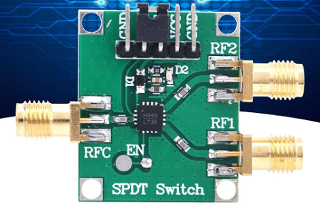
- Single Throw Double Pole Switch PCB: A printed circuit board (PCB) that integrates a switch component with two independent circuits (double pole) and only one switching position per circuit (single throw).
Functional Definitions of the Three Switches
1. Single Pole, Single Throw (SPST)
This is the most fundamental form of a switch, providing binary operation.
- Structure: It consists of one set of contacts (one movable contact and one stationary contact).
- Function: Its sole purpose is to open or close a single electrical path. It has two states: ON (closed) or OFF (open).
ON: Terminal 1 ↔ Terminal 2 (connected)
OFF: Terminal 1 ≠ Terminal 2 (disconnected)
- Application: Used for basic power switching—turning a circuit completely on or off (e.g., a power kill switch, a simple light circuit).
2. Single Pole, Double Throw (SPDT)
This switch adds the function of path selection or signal routing.
- Structure: It has one common movable contact and two stationary contacts. The common contact can be connected to either one of the two stationary contacts.
- Function: Routes one input circuit between two output paths. It connects a common terminal (COM) to either Terminal A or Terminal B. It typically has three states: Connect to A, Open (center-off), Connect to B.
COM ↔ Terminal A
COM ↔ Terminal B
(Note: Some SPDT switches include a center-off position where COM is disconnected from both A and B.)
- Application: Used for selecting between two sources or paths (e.g., switching an audio amplifier’s input between a CD player and a radio tuner, selecting a device’s operating mode).
3. Double Pole, Double Throw (DPDT)
This is a compound switch enabling synchronous control of two independent circuits.
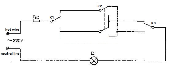
- Structure: It contains two independent sets of SPDT contacts. The switching mechanisms for both sets are mechanically linked and operated by a single actuator. Each side of a DPDT switch functions like an individual SPDT switch, so it can effectively be used as two SPDT switches. K2 is a Double Pole Double Throw (DPDT) switch, while K1 and K3 are Single Pole Double Throw (SPDT) switches.
- Function: It simultaneously switches the operating states of two independent circuits. It can synchronously change Circuit 1 and Circuit 2 from one connection mode (e.g., A1–A2) to another mode (e.g., B1–B2).
- Application:
- Motor control: Reversing the direction of a DC motor by swapping the polarity of the power connection to its terminals.
- Signal routing: Switching a stereo audio signal, routing both the left and right channels to different destinations simultaneously.
| Feature | SPST PCB | SPDT PCB | DPDT PCB |
|---|---|---|---|
| Core Function | Make or Break a circuit | Select between two paths | Synchronous switching of two circuits |
| Primary Action | On/Off | Changeover | Polarity Reversal / Complex Switching |
| Key Differentiator | Basic switching | Adds selection | Adds synchronous control |
In essence:
- Use a DPDT PCB when you need to control the state of two circuits at once in a coordinated manner.
- Use an SPST PCB when you only need to connect or disconnect a circuit.
- Use an SPDT PCB when you need to choose between two paths for a single circuit.
What are the Features of Single Throw Double Pole Switch PCB?
From a design and application perspective, a high-quality DPST switch PCB offers the following five core characteristics:
1. Synchronous Dual-Channel On/Off Control
Essential Feature: With a single mechanical action, it synchronously controls two completely independent circuits to turn on or off at the same time. This is the fundamental difference compared with SPST (Single Pole Single Throw) and SPDT (Single Pole Double Throw) switches.
2. High Electrical Isolation and Safety
Key Metrics: The insulation resistance between the two contact sets (typically >100MΩ) and dielectric withstand voltage (e.g., AC 1500V for 1 minute) are exceptionally high. This allows safe and independent control of both the live (L) and neutral (N) lines, providing true power-level isolation that goes far beyond the safety of cutting only a single line.
3. Robust PCB-Integrated Structure
Mechanical Feature: The switch body is soldered directly onto the PCB through multiple pins, offering superior structural strength, vibration resistance, and fatigue durability compared with wire connections. The PCB serves as the base, providing resistance to torque and lateral stress, ensuring that pads remain intact even under frequent operation.
4. Excellent Current-Carrying and Voltage Endurance Performance
Electrical Parameters: The contact material (such as silver alloy) and structural design determine the rated current (e.g., 10A/125VAC, 5A/250VAC) and rated voltage. The copper trace width on the PCB must be matched accordingly to avoid thermal bottlenecks across the entire conduction path.
5. Standardized Packaging for Automated Production
Manufacturing Advantage: To support SMT or wave soldering processes, DPST switches typically adopt standardized pin spacing (e.g., 5.08mm, 7.62mm) and package dimensions. PCB layouts must strictly follow the recommended pad pattern and thermal profile for reflow soldering to maintain high yield.
All in all, a DPST switch PCB is not a simple on-off component. It is a mechatronic module optimized for high reliability and safety in dual-channel synchronous power control. Its characteristics revolve around five key dimensions: synchronization, isolation, robustness, high power handling, and manufacturability.
What are the Types of DPST Switch?
DPST (Double Pole Single Throw) switches are available in various forms to meet different functional and design requirements. Each type can be adapted for PCB mounting, which helps engineers maintain a clean layout and reduce wiring errors. The main types include:
1. Mechanical DPST Switch
Mechanical DPST switches are the most common type. They operate by physically opening and closing circuits through a mechanical structure. Typically, they feature a lever, knob, or toggle actuator. Rotating or pressing the actuator moves the internal contacts to connect or disconnect the circuits. This type is robust, reliable, and widely used in industrial or power applications.
2. Electronic DPST Switch
Electronic DPST switches represent a modern approach. Instead of mechanical contacts, they use semiconductor devices to control circuit switching. The operation is often via a button, touchscreen, or other electronic interface. This type offers faster response times, precise control, and enhanced durability, making it ideal for signal detection, automation, or safety-critical applications.
3. Common Form Factors of DPST Switches
- Push Button DPST Switch: Activated by pressing, suitable for reset functions or manual control.
- Toggle DPST Switch: Simple lever operation, commonly used for power mode selection.
- Slide DPST Switch: Compact sliding action, ideal for small electronics or dual-mode devices.
- Rocker DPST Switch: Ergonomic design, suitable for frequent on/off applications.
- Micro DPST Switch: High-precision, small footprint, excellent for signal detection and safety features.
Each form factor can be selected based on application requirements, PCB layout constraints, and desired user interaction.
What are the Usage of Single Throw Double Pole Switch PCB in PCB?
DPST (Double Pole Single Throw) switches are versatile components widely used in PCB design. Their ability to simultaneously control two independent circuits makes them ideal for multiple practical applications:
1. Power Control
DPST switches can disconnect both positive and negative lines at the same time, providing enhanced safety for electronic devices and reducing the risk of accidental shorts.
2. Signal Switching
They are well-suited for audio, communication, and control circuits that require simultaneous dual-path switching. This ensures consistent signal routing and minimizes signal interference.
3. Mode Selection
DPST switches can toggle between two operation modes of a device with a single action. This simplifies user interaction and reduces the number of components required for mode control.
4. Circuit Protection
By controlling two circuits together, DPST switches help prevent accidental overloads or short circuits. This adds an extra layer of protection to sensitive electronics.
Integrating DPST switches directly onto PCBs helps reduce wiring complexity, improve layout cleanliness, and enhance overall system reliability. This addresses common customer concerns about circuit failures, maintenance difficulties, and assembly errors.
DPST switches are widely applied across various electrical devices and systems:
- Home Appliances: Control of lights, sockets, and other household devices.
- Industrial Equipment: Control and protection of machines and production systems.
- Power Systems: Switching and protection of electrical circuits in power distribution networks.
By combining dual-circuit control with PCB integration, DPST switches offer both operational efficiency and enhanced safety across multiple sectors.
How Does a Single Throw Double Pole Switch Work on a PCB?
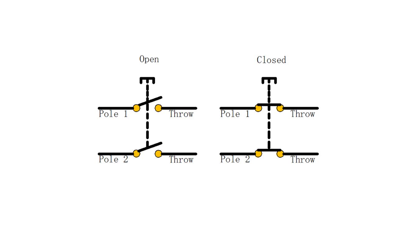
A DPST switch controls two independent circuits simultaneously through a single actuator. It operates in two basic states:
- Open (Off) State: In this state, the moving contacts are separated from the fixed contacts, and no current flows between the two terminals. The circuit is effectively disconnected.
- Closed (On) State: When the switch is actuated, the moving contacts make firm contact with the fixed contacts, completing the circuit and allowing current to flow.
The actuator—commonly a lever, knob, or toggle—moves the contacts from one position to another, enabling simultaneous switching of both circuits. This dual-path control ensures consistent operation for applications requiring synchronized circuit management.
How It Connects and Operates on a PCB?
When integrated on a PCB, the DPST switch is typically soldered directly onto designated pads via multiple pins. This setup provides several key benefits:
- Mechanical Stability: The PCB acts as a solid base, supporting the switch against torque and lateral forces. This prevents loosening or pad damage, even under frequent switching.
- Electrical Reliability: Each pole connects to PCB copper traces sized according to the switch’s rated current and voltage. Proper trace width ensures safe current flow and prevents overheating.
- Operational Simplicity: Users actuate the switch through its handle or lever, which moves both poles simultaneously. The PCB layout guarantees clean routing for both circuits, minimizing cross-talk and interference.
Advantages of Integrating a DPST Switch Directly on a PCB
Choosing PCB-mounted DPST switches instead of traditional wire-based connections provides multiple advantages:
- Reduced Wiring Complexity: Direct soldering eliminates the need for extra wires, reducing assembly errors and cluttered layouts.
- Enhanced Safety and Reliability: With a DPST switch controlling two circuits simultaneously, power lines can be fully isolated, improving overall system safety.
- Ease of Maintenance: Fewer discrete connections mean lower chances of loose connections or accidental shorts. Troubleshooting becomes faster and more straightforward.
- Support for Automated Manufacturing: Standardized pin spacing and pad layouts allow seamless integration with SMT and wave soldering processes, ensuring consistent quality and high production yield.
To sum up, on a PCB, a DPST switch is more than a simple on-off component. Its dual-circuit control, robust PCB integration, and standardized design make it a reliable and safe solution for applications that require synchronized operation of two independent circuits.
How to Select the Right DPST Switch for Your PCB Project?
For engineers and procurement specialists, selecting the correct DPST (Double Pole Single Throw) switch is a critical decision that impacts product safety, reliability, and manufacturability. This guide provides a focused, actionable framework for evaluation.
1. Define Electrical Requirements
- Voltage/Current Rating:
- AC/DC: Specify whether your application is AC or DC. The switch’s rated voltage and current must exceed the system’s maximum operating values.
- Load Type: This is critical. Derate heavily for inductive loads (e.g., motors, relays). A switch rated for 5A resistive load may only be suitable for a 1-2A inductive load due to inrush currents.
- Contact Resistance: Target <20 mΩ for power applications and <50 mΩ for signal-level switching to minimize heat generation and signal loss.
- Isolation & Dielectric Strength: For safety-critical isolation (e.g., switching both Line and Neutral), verify dielectric strength (e.g., >1500VAC for 1 minute) and insulation resistance (e.g., >100 MΩ).
2. Match Mechanical & Physical Specifications
- Mounting Style:
- Through-Hole (THT): Provides superior mechanical strength and solder joint reliability. Preferred for most applications.
- Surface-Mount (SMD): Saves board space but requires careful inspection of mechanical stability, especially under repeated actuation.
- Terminal Pitch & Footprint: Ensure the pin spacing (e.g., 5.08mm, 7.62mm) and overall footprint exactly match your PCB layout. Always use the manufacturer’s recommended land pattern.
- Actuator Type: Choose (Toggle, Rocker, Pushbutton) based on human-machine interface (HMI) design, panel cutout, and user experience requirements.
3. Evaluate Reliability and Lifetime
- Electrical Life (Cycle Life): This is the key metric. Ignore mechanical life. Check the datasheet for the number of cycles at your specific rated load (e.g., “10,000 cycles at 5A/250VAC”).
- Contact Material: Silver Alloy contacts (e.g., AgSnO₂, AgCdO) offer superior resistance to arcing and welding compared to pure silver, especially for inductive loads.
- Housing Material: Must be made of high-temperature, flame-retardant plastic (e.g., PBT, PA66 rated UL 94V-0).
4. Verify Environmental Compliance and Certifications
- IP Rating: Determine the required level of ingress protection (e.g., IP67 for dust and water resistance) based on the operating environment.
- Safety Certifications: Mandatory. The switch must carry the required certifications for your target market (e.g., UL/cUL, TUV, CE, CQC). Do not proceed without this.
Actionable Selection Checklist
| Parameter | Key Question / Action |
|---|---|
| Load Type | Is my load resistive or inductive? (If inductive, derate current rating significantly). |
| Ratings | Are the voltage/current ratings above my max operating values? (Confirm for both AC and DC). |
| Safety | Does the dielectric strength meet my safety isolation requirements? (Check >1500VAC). |
| Certifications | Does it have the necessary end-product safety certifications? (UL, CE, etc.) |
| Footprint | Does the pin pitch match my PCB layout? (Verify with manufacturer’s drawing). |
| Mounting | Is through-hole or SMD better for my assembly process and reliability needs? |
| Environment | What IP rating do I need for my product’s operating environment? |
| Samples | HAVE I ORDERED SAMPLES TO TEST FIT, FEEL, AND FUNCTION? |
Final Expert Advice:
- Always get samples. Physically test the switch in your actual application circuit and environment.
- Engage supplier FAEs early. Provide them with your exact application details (voltage, current, load type) for tailored recommendations.
- Specify clearly on your BOM. Beyond the part number, add descriptors (e.g., “DPST, 5A/250VAC, Toggle, THT, UL Listed”) to prevent procurement errors.
Wiring and Diagrams for DPST Switches on PCB
A DPST (Double Pole Single Throw) switch is essentially two independent SPST switches mechanically linked to operate simultaneously with a single actuator.
CRITICAL: Always verify pinout with manufacturer datasheet! Below shows the most common configuration.
| Pin # | Terminal Name | Function |
|---|---|---|
| 1 | NO1 (Normally Open 1) | Output for first circuit |
| 2 | COM1 (Common 1) | Input for first circuit |
| 3 | NO2 (Normally Open 2) | Output for second circuit |
| 4 | COM2 (Common 2) | Input for second circuit |
Operation: When switch is actuated, COM1 connects to NO1 simultaneously with COM2 connecting to NO2.
1. Essential Wiring Diagrams
- Application 1: Safety Power Disconnect (Line/Neutral Switching)
Complete AC Power Isolation
AC Input          DPST Switch          PCB Load
   L o───────┬─────| COM1   NO1 |──────┬─────[FUSE]─────▶ (Board VCC)
             │     |           |       │
             │     └───────────┘       │
   N o───────┼─────| COM2   NO2 |──────┴───────────────▶ (Board GND)
             │     |           |
             │     └───────────┘
Implementation Rules:
- AC input → Switch COM terminals → NO terminals → Fuse → Load
- Maintain ≥3.2mm creepage between L and N traces (250VAC)
- Place fuse AFTER switch for complete circuit protection
- Application 2: Dual Circuit Synchronous Control
Independent Circuit Control
Power Source 1 ────| COM1   NO1 |─────▶ Device 1 (e.g., 24V Motor)
                   |           |
Power Source 2 ────| COM2   NO2 |─────▶ Device 2 (e.g., 5V LED Indicator)
                   └───────────┘
Implementation Rules:
- Maintain complete electrical isolation between circuits unless designed otherwise
- Add RC snubber circuits at NO terminals for inductive loads
- Include local decoupling capacitors near load connections
2. PCB Layout Engineering Rules
Mechanical Implementation
- Mounting: ALWAYS use mechanical fasteners – solder joints alone won’t survive repeated actuation
- Strain Relief: Add M3 mounting holes at switch corners for panel mounting
- Orientation: Position actuator perpendicular to board flex direction
Trace Routing
- Current Capacity: Minimum 2.5mm trace width for 10A current (2oz copper)
- Routing Priority: Keep power traces short and direct – avoid 90° angles
- Isolation: Maintain ≥3.2mm clearance between high-voltage traces
Silkscreen Requirements
- Outline switch body with clear boundary
- Label all pins (COM1, NO1, COM2, NO2) adjacent to pads
- Mark ON/OFF positions relative to actuator
- Add rated specifications (V/A) near component
3. Pre-Fabrication Checklist
- Verified footprint against manufacturer datasheet (pin spacing critical)
- Confirmed creepage/clearance distances meet safety standards
- Added mechanical mounting holes with proper keepout zones
- Derated current handling for inductive loads (50-70% of nominal rating)
- Included snubber circuits for motor/relay loads
- Silkscreen includes pin labels and ON/OFF indicators
- Performed 1:1 print verification of component placement
4. Pro Tips from the Field
Reliability Enhancement: Apply silicone conformal coating around switch base to prevent dust ingress in high-cycle applications
Thermal Management: For high-current applications (>5A), connect multiple vias to internal ground planes under COM/NO pads
Safety First: Always implement redundant isolation methods (slot cuts, guard traces) when switching mains voltage
How Does a DP Switch Work?
A Double Pole Single Throw (DPST) switch operates based on the following principles and states:
1. Open Circuit State (Off Position)
- When the DPST switch is in the open circuit state, the moving contacts are separated from the fixed contacts. There is no electrical path between the two terminal pairs, preventing current flow through either circuit. Current can only pass through the switch when the operating mechanism is activated to transition it to the closed state.
2. Closed Circuit State (On Position)
- When the DPST switch is in the closed state, the moving contacts make physical and electrical contact with the fixed contacts. This creates a complete conductive path between both pairs of terminals, allowing current to flow simultaneously through both independent circuits.
3. Switching Operation
- The DPST switch features an operating mechanism, typically a toggle lever, rocker, or rotary knob. When this actuator is manipulated, it mechanically moves both contact poles simultaneously from their open positions to closed positions (or vice-versa). This synchronized action ensures both circuits are switched concurrently, maintaining identical states in both paths at all times.
The key operational characteristic is that both poles are mechanically linked to operate in unison with a single control action, providing simultaneous make-or-break operation for two separate circuits.
In summary, the single throw double pole switch PCB is an indispensable component for safe, reliable, and efficient circuit control. The blog aims to provide engineers and designers with a comprehensive understanding of DPST PCB, helping them make informed decisions when integrating these switches’ PCB into their projects. If you need any PCBs, just feel free to reach out to us at sales@bestpcbs.com.
FAQs
1. What’s the difference between SPDT and DPDT?
- SPDT (Single Pole Double Throw): Controls one circuit and can connect a single input to one of two outputs (e.g., input C → output D1 or D2).
- DPDT (Double Pole Double Throw): Controls two independent circuits simultaneously. Each pole works like an SPDT switch, so it can switch two inputs at the same time (e.g., input A1→A2 and input B1→B2). Each circuit has two destination options (double throw), and the switching of the two circuits is mechanically linked and synchronized. Essentially, a DPDT is like two SPDT switches operated together.
2. Can a DPDT be used as an SPDT?
- Yes. A DPDT switch can act as an SPDT by using only one of its two poles. The other pole can remain unused or be connected to perform a separate function. This makes DPDT switches versatile in applications where either single or dual circuit switching is needed.
3. What are the four types of switches?
- Switches are generally categorized based on pole and throw:
- SPST (Single Pole Single Throw) – Simple ON/OFF switch for a single circuit (e.g., A–B).
- SPDT (Single Pole Double Throw) – Switches one input between two outputs (e.g., C→D1 or D2).
- DPST (Double Pole Single Throw) – Switches two independent circuits simultaneously ON or OFF (e.g., A1→B1, A2→B2). A1→B1 represents the first circuit: when closed, current flows from A1 to B1. A2→B2 represents the second circuit: when closed, current flows from A2 to B2.
- DPDT (Double Pole Double Throw) – Switches two independent circuits between two sets of outputs simultaneously (e.g., A1→A2 and B1→B2).
For example: Previously: The upper path leads to A1, and the lower path leads to A2.
Afterward: They simultaneously change to the upper path leading to B1 and the lower path leading to B2.
To conclude, each path has two destination options (double throw), and the switching of the two paths is mechanically linked and synchronized.