





ESP32-C5 is a wireless microcontroller that brings 2.4 GHz and 5 GHz Wi-Fi 6 to connected products. For engineering teams, its appeal is the ability to use either Wi-Fi band while retaining a compact embedded platform. For production, the important distinction is whether the product uses the bare chip, a ready-made module, or a development board during evaluation—each leads to different purchasing, fabrication, and assembly requirements.
At EBest Circuit (Best Technology), we bring PCB manufacturing, component sourcing, and assembly together for custom electronics. For an ESP32-C5 product, that means building from your released hardware files and agreeing on inspection and functional testing before production. Send your board files, BOM, and intended quantities to sales@bestpcbs.com for a project-specific quotation.
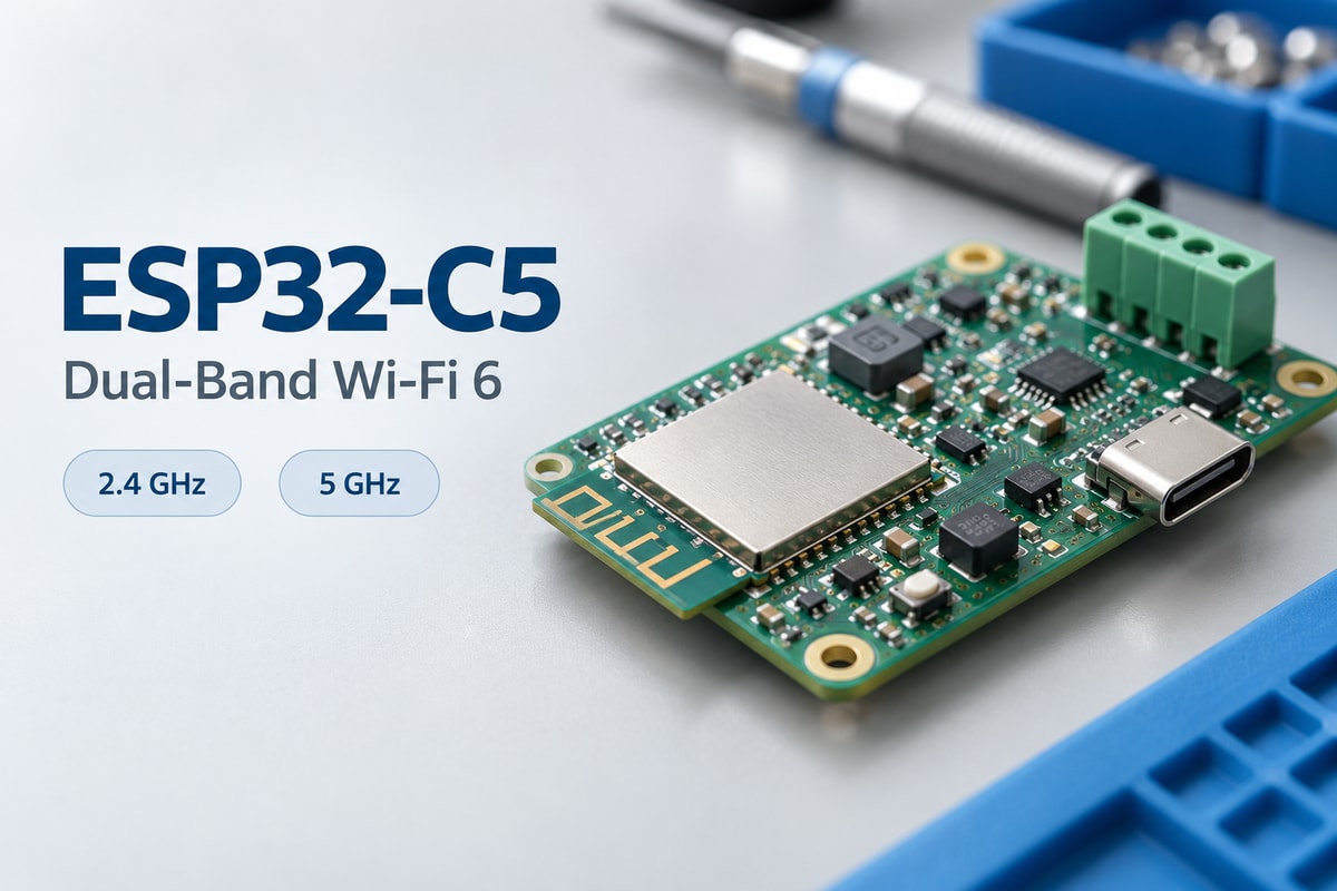
ESP32 C5 Features: Key Specifications for Product Selection
ESP32 C5 features combine a RISC-V processor, dual-band wireless connectivity, and interfaces for sensors and control electronics. The following specifications describe the chip family; module ordering codes and development-board versions determine the actual memory and accessible connections in a purchased product.
| Specification | ESP32-C5 capability |
|---|---|
| Main processor | Single-core 32-bit RISC-V, up to 240 MHz |
| On-chip ROM | 320 KB |
| High-performance SRAM | 384 KB |
| Low-power SRAM | 16 KB |
| Wi-Fi | 2.4 GHz and 5 GHz; Wi-Fi 6 / IEEE 802.11ax |
| Other wireless connectivity | Bluetooth LE and IEEE 802.15.4 for Thread and Zigbee |
| Chip-level GPIO count | 29; usable connections depend on package, memory configuration, and integration |
| Example peripheral interfaces | SPI, UART, I2C, I2S, SDIO slave, USB Serial/JTAG, and CAN FD |
| Package options | QFN48 or LGA48, 6 × 6 mm; part-number dependent |
| Flash and PSRAM | Configuration depends on the chip or module ordering code |
Memory capacity needs a complete part number. Flash stores firmware and persistent data; PSRAM provides additional working memory. Neither is interchangeable with the on-chip SRAM figures above. A BOM entry containing only “ESP32-C5” leaves the memory configuration and package unresolved.
ESP32 WiFi 6: What Does the C5 Add at 5GHz?
The C5 adds 5 GHz access to an ESP32 WiFi 6 product, providing an alternative when 2.4 GHz is congested. The improvement depends on the access point, signal strength, interference, and application traffic—not the band name alone.
- Band selection: A nearby access point with a cleaner 5 GHz channel may improve connectivity; 2.4 GHz can be more useful across distance and obstacles. Evaluate both with the intended enclosure, antenna orientation, and mounting surface.
- OFDMA and Target Wake Time: Wi-Fi 6 can organize traffic among compatible devices and support scheduled wake periods. Benefits depend on network support and configuration, so these features do not guarantee lower latency or power consumption in every installation.
- Connection limits: Dual-band capability does not mean two simultaneous independent Wi-Fi links or 5G cellular service. Firmware must support the intended access-point configuration and channels permitted in the operating region.
ESP32 C5 vs C6: Which Fits Your Connectivity Requirements?
The clearest difference in ESP32 C5 vs C6 selection is 5 GHz Wi-Fi support. Both provide Wi-Fi 6, so “Wi-Fi 6 required” alone does not establish a need for C5.
| Comparison | ESP32-C5 | ESP32-C6 |
|---|---|---|
| Wi-Fi bands | 2.4 GHz and 5 GHz | 2.4 GHz |
| Main CPU | RISC-V, up to 240 MHz | RISC-V, up to 160 MHz |
| Bluetooth LE | Supported | Supported |
| IEEE 802.15.4 | Supported | Supported |
| Thread and Zigbee | Supported with the appropriate software | Supported with the appropriate software |
| Strong reason to evaluate | Products that need access to 5 GHz Wi-Fi | Products whose wireless requirements are satisfied by 2.4 GHz Wi-Fi and/or 802.15.4 |
Selection beyond Wi-Fi: Choose C5 when deployment networks require 5 GHz or testing demonstrates its value; C6 remains relevant when 2.4 GHz meets the requirement. CPU clock alone does not predict performance—workload, memory, software, and network activity also matter.
Migration requirements: Review hardware and firmware when moving from C6 to C5. Similar family names do not establish pin-compatible replacement.
ESP32-C5 Module or Bare Chip: What Changes with ESP32-C5-WROOM-1?
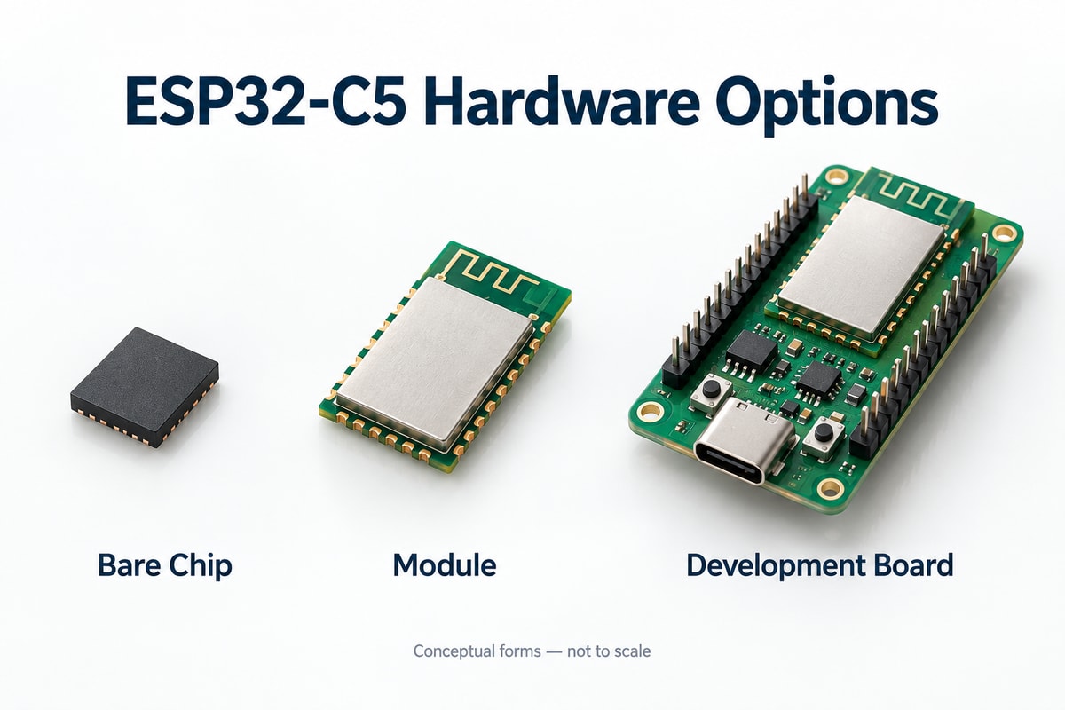
The main difference is how much wireless circuitry arrives as part of the purchased component. A bare chip leaves more integration on the custom PCB; a WROOM module packages the SoC, memory configuration, and supporting circuitry, but still needs a suitable host board and power supply.
| Hardware choice | Antenna arrangement | What changes for production |
|---|---|---|
| ESP32-C5 bare chip | Defined by the customer's RF implementation | Manufacture the released RF geometry and clock circuitry; assemble the chip and supporting components |
| ESP32-C5-WROOM-1 | Onboard PCB antenna | Use the module land pattern and preserve specified antenna clearances |
| ESP32-C5-WROOM-1U | External-antenna connection | Include the antenna, cable, mounting position, and connection operation in the assembly package |
GPIO and footprint selection: The WROOM family exposes up to 22 GPIOs, compared with 29 at chip level. Module pads, chip-package pins, and development-board headers are different references; the schematic symbol, footprint, and BOM must match the selected hardware.
An external antenna changes mechanical integration, not just the BOM. Neither antenna option eliminates the need to validate performance inside the finished enclosure.
ESP32-C5-DevKitC-1: What Can You Validate Before Building a Custom PCB?
ESP32-C5-DevKitC-1 lets you validate firmware, wireless behavior, and peripheral interfaces before releasing custom hardware. It combines a WROOM module with power circuitry, programming connections, buttons, and headers; those development-board features are not all included in the module itself.
- Network and firmware behavior: Test the intended access points, recovery after disconnection, application data transfer, and firmware updates. Record the settings and firmware version so the custom board can repeat the same checks.
- Peripheral operation: Exercise attached sensors and interfaces under realistic operating conditions. This establishes a useful reference when troubleshooting the first custom assembly.
- Power measurements: Regulator losses, LEDs, and the USB interface can contribute to board current. Measure the relevant supply rail rather than treating USB-input current as module consumption.
Repeat the relevant tests on the custom board and inside its enclosure. Changes to the supply, connectors, and antenna surroundings can affect behavior even with unchanged firmware.
ESP32 C5 Projects: Which Product Applications Benefit from Dual-Band Wi-Fi?
The strongest ESP32 C5 projects use dual-band connectivity to meet a deployment requirement. Connected appliances, indoor monitoring, building controls, and industrial communication interfaces are useful candidates when their networks and installation conditions justify 5 GHz support.
- Connected appliances: Support either Wi-Fi band available at the installation. Setup and reconnection behavior matter as much as initial connectivity.
- Indoor monitoring: Transfer logs or frequent measurements over a cleaner 5 GHz channel near an access point, where testing confirms an advantage.
- Building controls: Combine local sensing and control with Wi-Fi, Thread, or Zigbee. The software architecture determines how the device participates in the wider system.
- Industrial communication interfaces: Transfer local equipment data to a wireless network. The complete product still needs the appropriate isolation, protection, and physical-layer components.
A low-duty-cycle sensor with reliable 2.4 GHz coverage may gain little from 5 GHz. Coverage and antenna installation can outweigh Wi-Fi generation, particularly with distant access points or metal enclosures.
What PCB Materials and Manufacturing Controls Do ESP32-C5 Products Need?
ESP32-C5 boards need consistent reproduction of the approved stackup, copper geometry, and assembly features. Material selection follows the design's dielectric, thermal, and fabrication requirements; 5 GHz operation alone neither requires a specialty RF laminate nor justifies an arbitrary FR4 substitution.
- Layer count and stackup: Espressif recommends four layers in its chip-level layout guidance. A completed module's carrier board may have different requirements; agree the four-layer PCB stackup or other validated construction before fabrication.
- 50 Ω RF transmission lines: Where the board carries an RF feed line, use the specified characteristic impedance and approved stackup. Trace width depends on dielectric thickness and material properties, so a width copied from another board is insufficient.
- Antenna clearances and CAM control: Preserve copper keepouts, ground structures, solder-mask openings, and board-edge relationships. Panel supports or CAM copper additions must not encroach on released antenna regions; proposed changes require engineering approval.
- Finish, pads, and vias: Match the specified surface finish, pad geometry, and via treatment to the assembly process. Exposed ground pads and nearby vias need particular attention to prevent uncontrolled solder loss.
These controls reproduce the customer's validated hardware; they do not replace RF or antenna development.
How Do You Prepare an ESP32-C5 Board for PCB Assembly and Production Testing?
Prepare one consistent hardware revision, a complete purchasing specification, and a repeatable acceptance test. The ordered chip or module must match the BOM, footprint, and manufacturing files.
| Production input | Required detail |
|---|---|
| PCB fabrication package | Gerber and drill files, fabrication requirements, and approved revision |
| Assembly and procurement package | BOM with manufacturer part numbers, placement data, assembly drawings, relevant schematic, quantities, supplied parts, and explicit do-not-populate positions |
| Programming and test package | Firmware files, programming instructions, test connections, equipment requirements, and pass/fail limits |
Package-specific assembly controls: Stencil apertures, paste deposition, placement, and reflow must suit the actual package and BOM. Follow component storage, moisture-handling, and thermal requirements rather than applying a generic reflow profile.
Inspection versus functional testing: SPI checks paste deposits, AOI examines visible assembly features, and X-ray can inspect concealed joints where appropriate. These PCBA inspection and testing methods complement functional testing; they do not prove wireless performance.
For a repeatable C5 functional test, define:
- Power-up checks and firmware identification.
- Connection and data transfer on each required Wi-Fi band, using a defined access point and configuration.
- Operation of fitted interfaces, with a consistent fixture arrangement and acceptance limits.
Agree customer firmware, test equipment, and the required inspection scope with the assembler before finalizing the production quotation.
ESP32-C5 Case Study: From Prototype to PCB Assembly
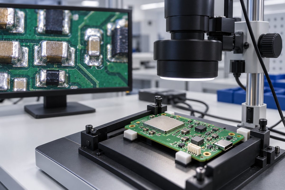
An EBest Circuit RF-interface order combined PCB fabrication, component sourcing, and SMT assembly for 20 boards. It provides the manufacturing basis for the ESP32-C5 wireless communication terminal discussed here; the C5 application is an adaptation, not an identified feature of the original order.
The terminal uses an ESP32-C5-WROOM-1 to collect local equipment data and send it over 2.4 GHz or 5 GHz Wi-Fi. Its carrier accommodates the power input and equipment connections. The recorded customer requirements included production-file approval and individual-board delivery after SMT.
| PCB parameter | Actual order specification |
|---|---|
| Construction | 4 layers; FR4, Tg130 |
| Finished thickness | 1.60 mm ±10% |
| Copper weight, L1–L4 | 1 / 0.5 / 0.5 / 1 oz |
| Surface finish | ENIG, specified gold thickness 1 µin |
| Mask and legend | Green solder mask; white silkscreen |
- Fabrication-to-SMT handoff: Our recorded scope included panelization and component procurement. The SMT order referenced the same PCB revision, connecting the bare-board specification with assembly and purchasing requirements.
- Customer release control: Production-file approval was required before fabrication. This gave the customer a defined review point for the manufacturing data rather than relying on a prototype description.
- C5 antenna integration: For the terminal adaptation, panel supports and nearby components must preserve the module's antenna clearance. The recorded stackup is a manufacturing reference; the carrier and enclosure need C5-specific validation.
- Inspection and test preparation: The C5 build requires module and power-circuit solder-joint inspection, programming, startup, interface checks, and data transfer on both required bands. Customer firmware, access-point settings, and pass/fail limits define the functional test.
The commercial value is a coordinated fabrication, sourcing, and SMT package with a controlled board revision. For the C5 terminal, adding the approved assembly and test instructions establishes a practical handoff for pilot and repeat builds.
Why Choose BestPCBS for ESP32-C5 PCB Manufacturing and Assembly?
BestPCBS combines PCB fabrication, sourcing, and assembly through EBest Circuit (Best Technology). Our PCB assembly service supports custom C5 hardware from a released manufacturing package through inspection and agreed testing.
- SMT and mixed assembly: SMT and through-hole processes accommodate modules, compact supporting components, and wired connectors on the same product.
- DFM and assembly review: We review fabrication data, stackup requirements, and assembly inputs to identify manufacturing issues before production.
- Component sourcing: Full turnkey, partial turnkey, and consignment options let you choose which parts we procure. Manufacturer and authorized-distributor sourcing supports BOM control.
- SPI, AOI, and X-ray: Our equipment includes 3D solder paste inspection, 3D AOI, and X-ray inspection for relevant joint types. Inspection scope follows the assembly's risks and acceptance requirements.
- Functional test support: We coordinate testing around your firmware, connections, and acceptance limits, connecting assembly checks with product operation.
- Quality management: ISO 9001:2015 is among our listed quality certifications. Project-specific documentation and acceptance requirements belong in the agreed production scope.
FAQs About ESP32-C5
These questions cover purchasing, software compatibility, and hardware details that affect a C5 production build. Use the exact hardware version when checking compatibility or estimating cost and power.
What Affects the ESP32-C5 Price in a Production BOM?
The exact chip or module, memory configuration, antenna version, order quantity, and sourcing conditions affect component price. A development-board retail price is not a production module price. Compare quotations using the same ordering code, and separate component cost from PCB fabrication, assembly, programming, and test costs.
What Should You Check for ESP32-C5 Arduino Compatibility?
ESP32-C5 is listed as supported in the current Arduino-ESP32 stable and development support tables. Use a release that supports C5 and the appropriate board configuration. Peripheral libraries, flash settings, PSRAM settings, and upload behavior still need application-level testing; support for the SoC does not guarantee compatibility with every library written for another ESP32 device.
Where Should You Check the ESP32 C5 Pinout for Your Exact Hardware?
Use the chip datasheet for package pins, the selected module datasheet for module pads, and the development-board schematic and header table for board connections. Match the hardware revision. A classic ESP32-WROOM or generic 30-pin diagram should not be used as a C5 pin reference.
How Should You Evaluate ESP32 Power Consumption for a C5 Battery-Powered Product?
Measure the complete product through its actual operating cycle, including wake-up, sensing, network connection, transmission, and sleep. Battery life depends on the time spent in each state, regulator losses, and peripheral loads. A chip sleep-current figure alone does not represent the average current of a finished product.
Does the ESP32-C5 TWAI Controller Need an External CAN Transceiver?
Yes. Connection to a physical CAN bus requires an external transceiver. The controller handles protocol functions; the transceiver provides the bus interface. Match the transceiver, protection circuitry, termination, and firmware configuration to the required bus implementation, including CAN FD where applicable.
Does Using ESP32-C5-WROOM-1U Remove the Need for Final-Product RF Validation?
No. The external antenna, cable, enclosure, and mounting arrangement can affect wireless performance. Validate the finished assembly in the intended configuration and operating environment. Replacing an antenna or changing its mounting position can require renewed evaluation.
Bring your ESP32-C5 manufacturing package to EBest Circuit for a quotation covering PCB fabrication, component sourcing, assembly, and the agreed testing scope. Email the files, quantities, and target delivery date to sales@bestpcbs.com so we can assess the build around your actual hardware configuration.
You may also like
Tags: ESP32 PCB Assembly, ESP32-C5