





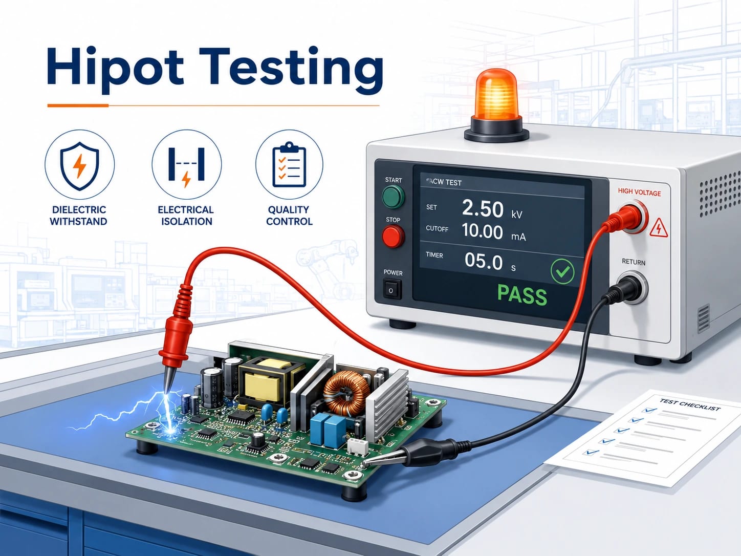
Hipot testing, also known as high potential testing or dielectric withstand testing, checks whether an electrical insulation barrier can withstand a specified high voltage without breakdown, flashover, or excessive leakage current.
The test is commonly used in power supplies, transformers, cables, wire harnesses, mains-powered PCB assemblies, medical electronics, industrial controls, and other products where hazardous voltage must remain isolated from users or low-voltage circuits.
A valid hipot test requires more than a voltage value. The test plan should define the waveform, test points, ramp time, dwell time, current limit, discharge method, and acceptance criteria.
What Is Hipot Testing?
Hipot is short for high potential. During the test, a voltage higher than the normal operating voltage is applied between conductive areas that should remain electrically isolated.
Typical test points include:
- Primary circuit to secondary circuit
- Live conductors to a metal enclosure
- Transformer winding to winding
- Transformer winding to core
- Cable conductor to shield
- High-voltage circuit to low-voltage control circuit
The tester monitors current through the insulation barrier. The product passes when it withstands the required voltage for the specified time without excessive current, arcing, flashover, or insulation breakdown.
Hipot testing is usually a pass-or-fail safety test. It does not replace insulation resistance measurement, ground bond testing, leakage current testing, functional testing, or partial discharge analysis.
What Is the Purpose of Hipot Testing?
The purpose of hipot testing is to confirm that an insulation barrier can tolerate a controlled electrical stress above normal operating conditions.
The test can expose defects that may remain hidden during a standard power-on inspection, such as:
- Damaged wire insulation
- Conductive contamination on a PCB
- Insufficient spacing between conductors
- Pinched wires inside an enclosure
- Incorrect insulation films or sleeves
- Transformer winding defects
- Solder bridges near an isolation gap
- Cracked or poorly fitted insulating parts
For PCB assemblies, hipot testing is mainly relevant when the board contains a safety isolation boundary. A low-voltage control board powered by a certified SELV source may not need board-level testing. An AC/DC power supply PCBA, however, usually requires dielectric withstand verification between the mains side and the isolated output.
Passing the test confirms insulation withstand capability. It does not automatically prove compliance with creepage, clearance, protective earthing, flammability, or operating leakage-current requirements.
How Does Hipot Testing Work?
A hipot tester combines a controlled high-voltage source with a current-measurement circuit. The voltage is applied across the insulation barrier being evaluated.
For an isolated power supply, line and neutral may be connected together as one test node. The voltage is then applied between that node and the secondary output. The exact connection must follow the product standard and approved test instruction.
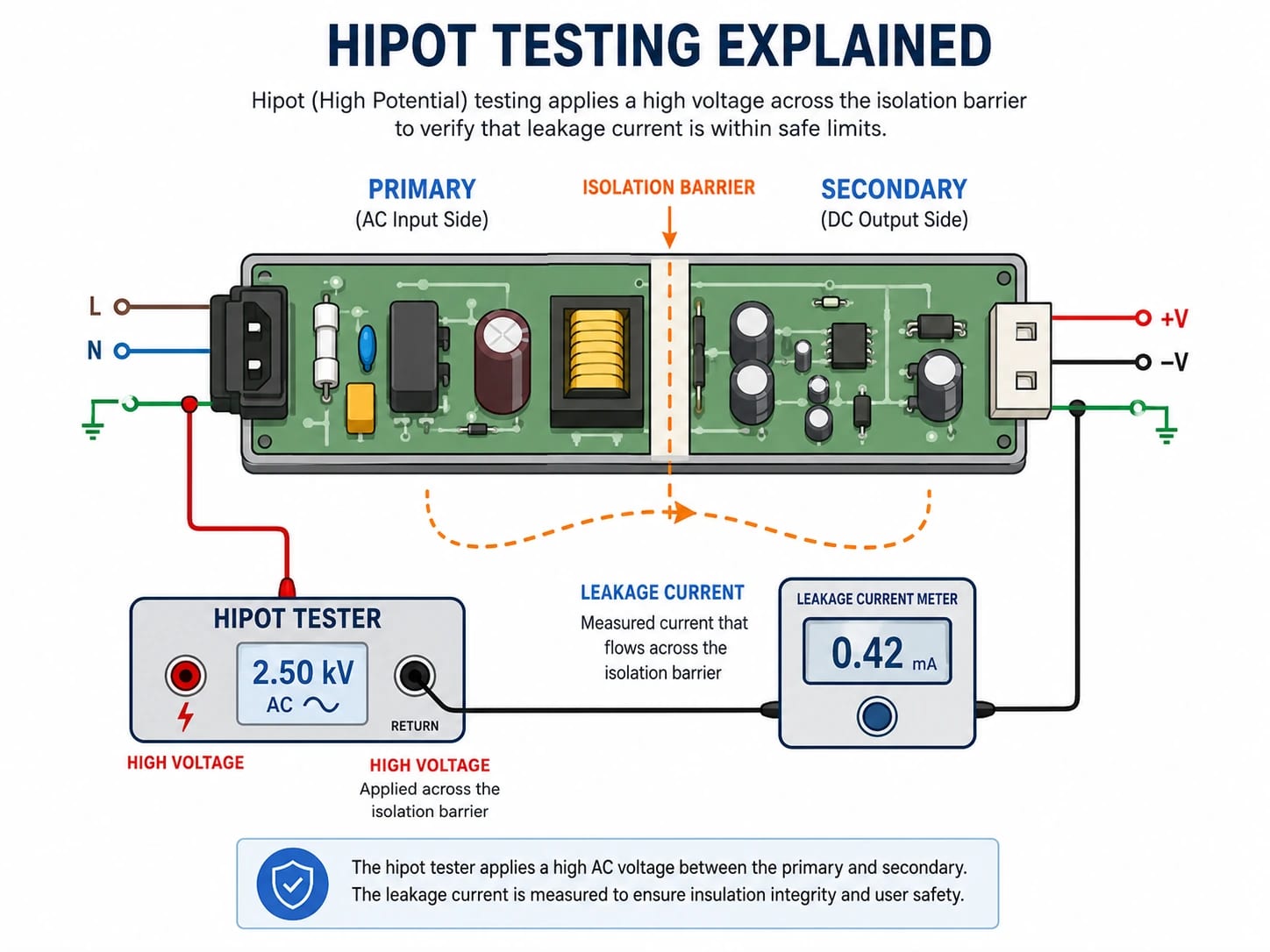
A typical test has four stages:
- Ramp the voltage from zero to the target level.
- Hold the voltage for the specified time.
- Monitor current, flashover, and breakdown.
- Reduce the voltage to zero and discharge the DUT.
The measured current may include normal capacitive current, current through EMI capacitors, surface leakage, and current through the insulation itself.
This is why the current limit must match the product. A limit that is too low may reject acceptable assemblies. A limit that is too high may allow a real defect to pass.
What Is the Difference Between AC and DC Hipot Testing?
AC and DC testing stress insulation differently. The applicable product standard should determine which method is used.
| Comparison | AC Hipot Testing | DC Hipot Testing |
|---|---|---|
| Waveform | Alternating polarity | Single polarity |
| Current behavior | Includes continuous capacitive current | High initial charging current, then lower steady current |
| Tester capacity | May require higher output power | Often requires less power after charging |
| Residual charge | Usually lower, but still possible | DUT may retain a hazardous charge |
| Discharge | Required where stored energy remains | Essential after every test |
| Typical use | Product safety and production testing | High-capacitance products where permitted |
| Main concern | Capacitive current may cause nuisance trips | Poor discharge control creates shock risk |
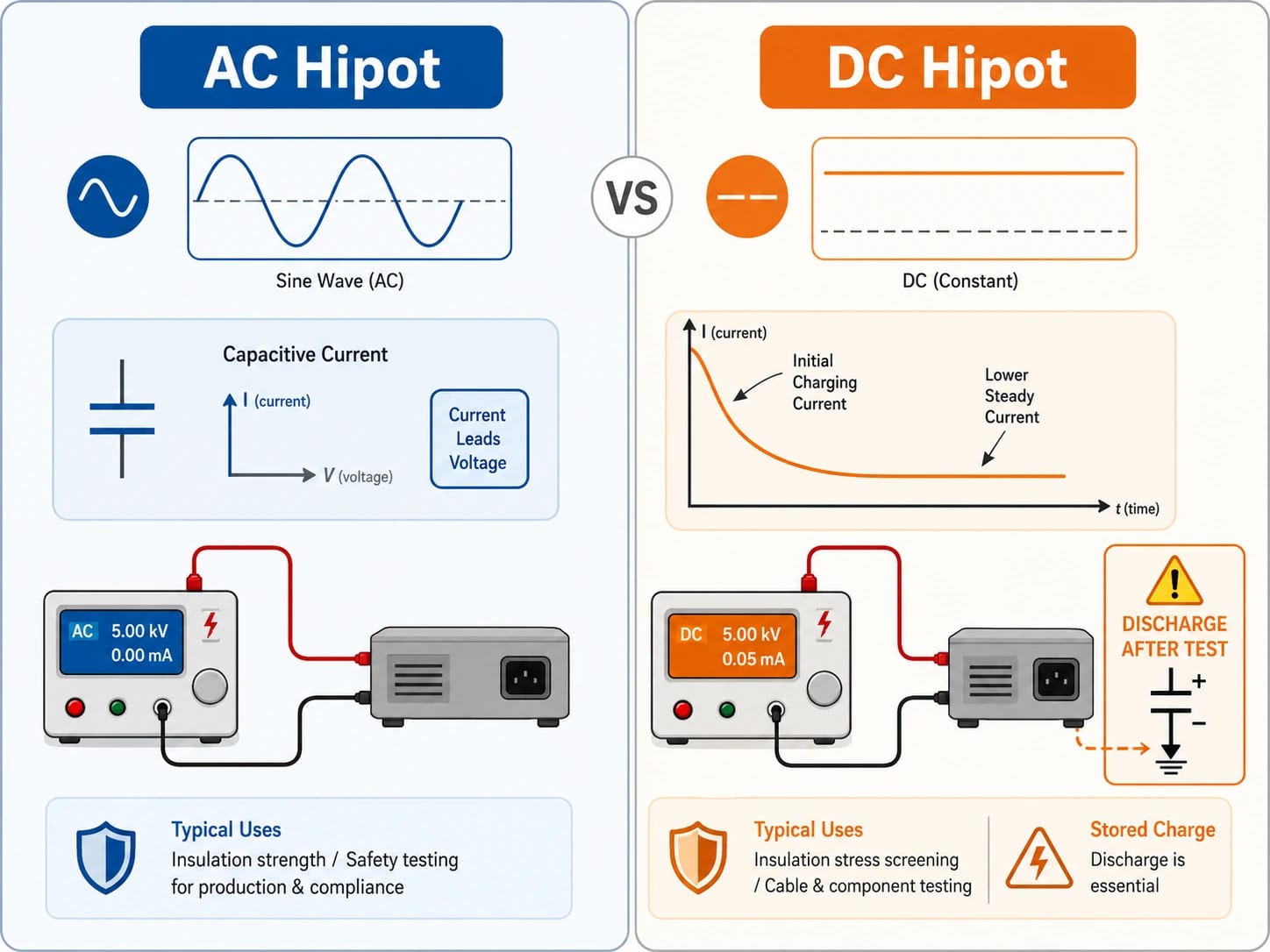
AC testing repeatedly reverses the electric field. Products containing long cables, large windings, or EMI capacitors may draw considerable reactive current.
DC testing charges the product in one direction. Steady leakage can be easier to observe after the charging current settles, but the DUT may remain charged after the source is removed.
An AC requirement should not be converted into a DC value unless the applicable standard permits the substitution.
How Is Hipot Testing Voltage Determined?
There is no universal hipot testing voltage or formula.
The correct value depends on the product standard, working voltage, insulation classification, test location, waveform, test duration, and destination market.
| Factor | Effect on Test Selection |
|---|---|
| Working voltage | Higher operating voltage generally requires stronger insulation |
| Insulation type | Basic, supplementary, double, and reinforced insulation have different requirements |
| Test path | Primary-to-secondary and primary-to-chassis tests may differ |
| AC or DC | Waveform and peak voltage affect insulation stress |
| Type or routine test | Certification and production testing may use different conditions |
| Product category | Medical, household, industrial, and AV/ICT products follow different standards |
| Test duration | Some standards allow shorter production tests at adjusted voltage |
| DUT capacitance | Affects charging current and tester capacity |
| Market | IEC, UL, CSA, and EN requirements may differ |
For production planning, “hipot required” is not enough. The customer should provide:
- AC or DC voltage
- Target voltage
- Ramp time
- Dwell time
- Upper current limit
- Lower current limit, if required
- Test points
- Arc-detection requirement
- Discharge time
- Sampling rate or 100% testing
- Applicable standard and edition
These parameters affect fixture design, equipment selection, cycle time, and quotation cost.
What Equipment Is Required for Hipot Testing?
The main instrument is a hipot tester, also called a dielectric strength tester. The right model should be selected according to the actual product and test program rather than maximum voltage alone.
Key specifications include:
- Maximum AC and DC output
- Output power
- Leakage-current range
- Current resolution and accuracy
- Programmable ramp and dwell time
- Upper and lower current limits
- Arc detection
- Automatic discharge
- Residual-voltage indication
- Safety interlock input
- Data logging
- Barcode or MES connection
- Multi-channel scanning
A production workstation may also require an interlocked safety enclosure, insulated fixture, warning indicators, emergency stop, two-hand start control, automatic data capture, and a scanner for multiple test points.
Portable hipot testing kits are useful for some controlled field applications. For repetitive factory use, a guarded fixture with interlocks and traceability is usually more suitable.
What Is the Hipot Testing Procedure?
The approved procedure should follow the applicable product standard. A practical sequence is shown below.
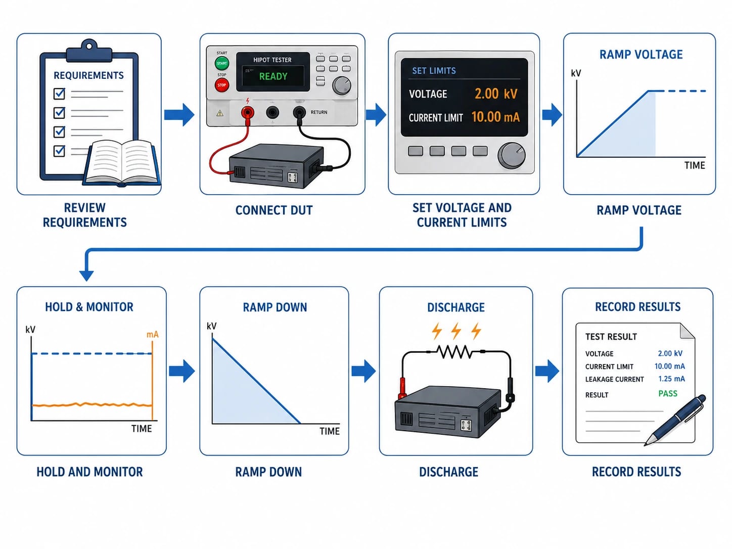
- Confirm the requirements. Review the waveform, voltage, test points, ramp time, dwell time, current limits, and pass criteria.
- Remove normal power. Disconnect the DUT from its operating supply and control stored energy.
- Inspect the product and fixture. Look for damaged insulation, moisture, contamination, loose connections, and fixture wear.
- Prepare the circuit. Close switches or connect terminals as required so the test reaches the intended insulation paths.
- Connect the return lead. Make the low-side connection before attaching the high-voltage lead.
- Program the tester. Set the waveform, voltage, current limits, timing, arc detection, and discharge period.
- Secure the test area. Close the enclosure, verify the interlock, and activate warning indicators.
- Ramp the voltage. Increase the voltage at the approved rate.
- Hold and monitor. Observe leakage current, flashover, abnormal sound, visible arcing, smoke, or unstable output.
- Ramp down and discharge. Return the voltage to zero and complete the discharge cycle.
- Verify zero residual voltage. Do not touch or disconnect the DUT until stored charge has been removed.
- Record the result. Save the serial number, program version, measured current, voltage, test time, operator, and result.
For production use, the procedure should be issued as a controlled work instruction. Operators should not change test parameters without engineering approval.
How Are Hipot Test Results Evaluated?
A product passes when it reaches the specified voltage, remains there for the required time, and stays within the approved current limit without breakdown or flashover.
| Result | Likely Meaning |
|---|---|
| Stable current below the limit | Insulation withstood the test |
| Immediate high-current trip | Short circuit, incorrect connection, or severe insulation failure |
| Rising current during the dwell period | Moisture, contamination, heating, or developing breakdown |
| Brief arc event | Insufficient clearance, contamination, or a sharp conductive feature |
| Trip during ramp-up | Excessive charging current, unsuitable ramp rate, or weak insulation |
| Unstable output voltage | Tester capacity issue, fixture problem, or abnormal DUT loading |
There is no universal acceptable leakage-current value. The limit depends on the standard, test voltage, waveform, product capacitance, and intentional components across the isolation barrier.
A failed unit should be investigated rather than immediately classified as a false trip. Useful checks include:
- Test the fixture with a known-good sample.
- Inspect isolation slots and board edges.
- Check for flux residue beneath transformers and optocouplers.
- Confirm the test nodes.
- Review EMI capacitors connected across the barrier.
- Check transformer orientation and winding insulation.
- Verify the ramp rate and current range.
Repeated failures at the same location often indicate a design, cleanliness, or process-control issue rather than random operator error.
What Safety Requirements Apply to Hipot Testing?
Hipot testing intentionally creates a hazardous voltage. The DUT, fixture, test leads, and internal capacitors may remain charged after the active test ends.
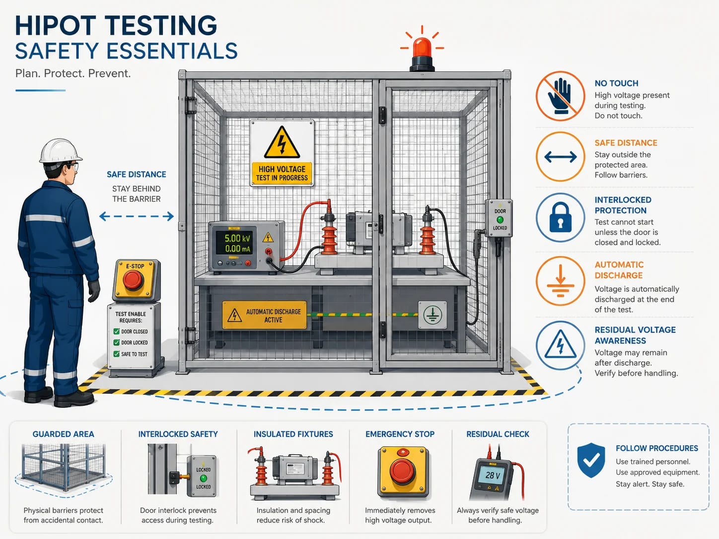
A safe workstation should include:
- Trained and authorized operators
- A guarded test area
- Door or cover interlocks
- High-voltage warning lights
- An accessible emergency stop
- Insulated fixtures and cables
- Automatic ramp-down
- Automatic discharge
- Residual-voltage verification
- Documented maintenance procedures
- Regular inspection of leads and fixtures
The operator should never touch the DUT simply because the tester shows “PASS.” The output must return to zero, the discharge cycle must finish, and any stored voltage must be checked.
An interlock is only one layer of protection. It does not replace a proper enclosure, operator training, fixture maintenance, grounding, or a controlled test procedure.
Which Hipot Testing Standards Apply?
The applicable standard depends on the final product, market, operating environment, and user-accessible circuits. A PCB assembly normally follows the safety requirements of the finished equipment.
| Product or Application | Common Standards Direction |
|---|---|
| Audio, video, IT, and communication equipment | IEC 62368-1 and regional versions |
| Medical electrical equipment | IEC 60601-1 and applicable particular standards |
| Measurement and laboratory equipment | IEC 61010-1 and relevant Part 2 standards |
| Household appliances | IEC 60335-1 and applicable Part 2 standards |
| Machinery electrical equipment | IEC 60204-1 |
| Hipot and insulation test equipment | IEC 61010-2-034 |
| Shielded power cables rated 5 kV and above | IEEE 400 series |
| VLF cable testing | IEEE 400.2 |
| Custom industrial equipment | Customer specification plus applicable regulatory standard |
The standard edition accepted by the certification body and destination market should be confirmed before production. A recently published edition may not yet be mandatory in every region.
Legacy formulas or requirements from withdrawn standards should not be copied into a new test plan without checking whether they still apply.
Hipot Testing vs Insulation Resistance Testing: What Is the Difference?
The two tests both evaluate insulation, but they answer different questions.
| Comparison | Hipot Testing | Insulation Resistance Testing |
|---|---|---|
| Purpose | Verify dielectric withstand capability | Measure insulation resistance |
| Result | Pass or fail | Resistance value |
| Stress level | Usually higher | Usually lower |
| Main measurement | Leakage current and breakdown behavior | Resistance in MΩ or GΩ |
| Common use | Product safety and production testing | Maintenance and insulation condition checks |
| Instrument | Hipot tester | Megohmmeter or insulation resistance tester |
“Megger test” is often used as another name for insulation resistance testing, although Megger is also an equipment brand.
A high insulation resistance reading does not guarantee that a product will pass a hipot test. A passed hipot test also does not provide the resistance trend needed for preventive maintenance.
Where both tests are required, they should remain separate steps with separate limits.
Hipot Testing vs VLF Testing: Which Is Used for Cables?
VLF is a form of AC high-voltage testing performed at a frequency below normal power frequency. It is mainly used for shielded medium- and high-voltage power cable systems.
| Comparison | Power-Frequency AC Hipot | DC Hipot | VLF Testing |
|---|---|---|---|
| Frequency | Usually 50 or 60 Hz | 0 Hz | Below 1 Hz |
| Typical application | Electrical products and some cable systems | Applications permitted by the relevant standard | Shielded MV/HV cables |
| Cable loading | High on long cables | High charging current, then lower leakage | Lower power demand than 50/60 Hz AC |
| Residual charge | Possible | Significant | Discharge still required |
| Selection basis | Product standard | Product or cable standard | Cable standard and field-test plan |
Long cables behave as large capacitors. Testing them at 50 or 60 Hz can require a very large source. VLF reduces the continuous charging-current demand, making field testing more practical.
A factory hipot tester used for PCB assemblies should not be assumed suitable for cable commissioning. Cable voltage class, insulation material, accessories, installation history, and utility requirements must be considered.
How Is Hipot Testing Used for Cables, Wires and Transformers?
Low-voltage wires, shielded power cables, and transformers require different connections and acceptance criteria.
For low-voltage cables and wire harnesses, common test paths include:
- Conductor to conductor
- Conductor to shield
- Conductors tied together to shield
- Conductor to connector shell
- High-voltage wire to low-voltage signal wire
- Conductor to protective earth
Hipot wire testing can detect damaged jackets, pinched insulation, incorrect pin assignments, stray wire strands, and defects inside overmolded connectors.
Medium- and high-voltage cable systems may require VLF withstand, tan delta, partial discharge, or another field-test method. These applications should follow the cable standard and utility test plan rather than a generic factory procedure.
Transformer testing may include:
- Primary winding to secondary winding
- Primary winding to core
- Secondary winding to core
- Separate secondary windings
- Winding to electrostatic shield
- Winding to accessible chassis
All terminals within one test group are normally connected together. The drawing, insulation system, and product standard should define the exact test nodes.
A transformer hipot test is not the same as an induced-voltage test, surge test, insulation resistance test, or partial discharge test.
Where Is Hipot Testing Used in Electronics Manufacturing?
Hipot testing is common in products that contain hazardous voltage or depend on galvanic isolation.
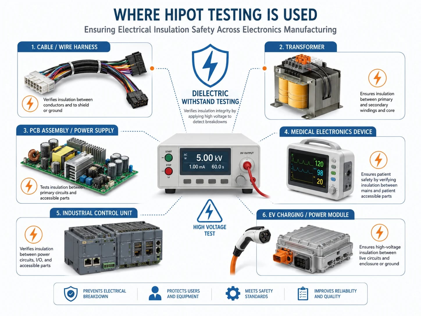
Typical applications include:
- AC/DC power supplies
- Chargers and adapters
- Medical electronics
- Industrial controls
- Household appliances
- Isolation transformers
- Motor drives
- EV charging equipment
- Battery energy storage systems
- High-voltage relays
- Isolated DC/DC converters
- Power distribution units
- Mains-powered PCB assemblies
For PCB and PCBA purchasing, the test requirement should be defined before quotation. Voltage, dwell time, current limits, fixture complexity, data logging, and production volume all affect cost and lead time.
Customers should provide:
- Final product type
- Target market
- Applicable safety standard
- Isolation-barrier drawing
- PCB or PCBA test points
- Test voltage and waveform
- Ramp and dwell time
- Leakage-current limits
- Arc-detection requirement
- Production quantity
- Traceability format
- Approved test instruction
The PCB layout should also be checked for creepage, clearance, isolation slots, board-edge spacing, contamination risk, transformer footprint, and high-voltage test access.
EBest Circuit can review PCB and PCBA manufacturing files against our PCB manufacturing capabilities and perform customer-defined tests using approved instructions. Clear test parameters should be supplied with the Gerber files, BOM, assembly drawings, and expected order quantity.
FAQs
Hipot testing means high potential testing. It applies a controlled high voltage across an insulation barrier to check whether the barrier can withstand the specified electrical stress.
It verifies dielectric strength and helps identify damaged insulation, inadequate spacing, contamination, pinched wires, and transformer defects.
The voltage depends on the product standard, working voltage, insulation class, waveform, test location, and duration. There is no single value for every product.
No universal formula applies to all equipment. Any calculation must be used within the scope of the standard that defines it.
The acceptable limit comes from the product standard or approved test plan. It must account for test voltage, DUT capacitance, waveform, and intentional components across the isolation barrier.
It is normally non-destructive when the correct voltage, duration, waveform, and current limits are used. Excessive voltage or repeated overstressing can damage insulation and sensitive components.
Hipot testing checks whether insulation can withstand a high-voltage stress. Insulation resistance testing measures the resistance of the insulation.
AC testing reverses polarity and produces continuous capacitive current. DC testing charges the DUT in one direction and requires careful discharge after the test.
VLF is a low-frequency AC method used mainly for shielded MV/HV cable systems. Hipot testing is a broader term covering dielectric withstand testing for many electrical products.
Common causes include insulation damage, contamination, insufficient clearance, moisture, transformer defects, pinched wiring, solder bridges, incorrect fixture connections, and unsuitable test settings.
Hipot testing provides useful evidence that an insulation barrier can withstand a defined electrical stress. Reliable results depend on the correct standard, voltage, waveform, test points, current limits, fixture, and safety controls.
For PCB or PCBA projects that require dielectric withstand testing, include the approved test parameters with the quotation package. Contact EBest Circuit at sales@bestpcbs.com to discuss PCB fabrication, assembly, engineering review, and production testing.
You may also like








Tags: hipot testing, hipot testing equipment, hipot testing procedure, hipot testing safety requirements, hipot testing standards