

A high speed DAC board is a critical component in advanced electronics, especially when systems require fast and precise digital-to-analog conversion. The key content of this blog is let you know the meaning, features, main types, design, applications of high speed DAC boards, and the core difference between an ADC and a DAC.
Have you experienced these operational difficulties?
- Real challenge of signal integrity?
- Major issues of heat dissipation and heat management?
- Big trouble with connection and compatibility?
- Fundamental problem of cost and maintenance?
- Particular obstacle to performance and stability?
These proper solutions effectively tackle the above challenges.
- Optimize PCB design and material selection: For example, use high-frequency material and optimize trace layout to enhance design; Adopt high-frequency copper wire and low-loss material to boost signal completeness and thermal dissipation. Besides, use the innovative PCB manufacturing process, such as multilayer board, high frequency board, to improve the integrated performance.
- Apply high speed DAC module and modular design: Improving compatibility and maintainability via using high speed DAC modules, high-speed DAC cables.
- Elevate thermal dissipation design: For example, adding heat sinks or implementing active cooling technology to address the heat dissipation problem of high speed DAC boards, ensuring stable operation in high loading.
- Use high-performance DAC chips and interface solutions: Use chips like AD9122, AD9715, and use interface solutions like ADL5375 I/Q modulator interface to meet transmission needs in high-speed data.
- Get technical support and training: It is beneficial to use and maintain highspeed DAC boards, and decrease defect rate and maintenance costs.
As a major PCB manufacturing factory in China, EBest Circuit (Best Technology) has the capability to support customizable design, low batch prototypes, medium manufacturing, mass production, SMT PCBA, and box building. Our factory has a rigorous management system, such as ISO 9001, IATF 16949, AS9100D, and ISO 13485. And you will got our complete inspection with your order, such as high-speed signal inspection, aging test, EMC evaluation, SPI, AOI, X-ray, and others. Pls rest assured that our boards do not have unstable quality or have quality differences between batches. If any new project would like to discuss more details with us, pls get in touch with us at sales@bestpcbs.com or call us at +86-755-2909-1601.
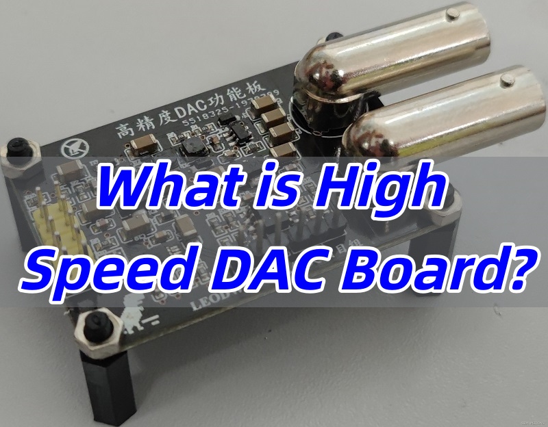
What is a high speed DAC board?
A high speed DAC board is a hardware platform designed to convert digital signals into analog signals at very high speeds. To make it easier for beginners to understand, let’s break it down step by step:
Basic Definition
DAC stands for Digital to Analog Converter. A DAC board integrates the DAC chip with supporting circuits such as power, filtering, clock, and signal conditioning on a single PCB. Its job is simple: turn digital signals (“0” and “1”) into continuous analog signals (voltage or current).
👉 Example: Music files in your phone are digital signals. But headphones and speakers need analog signals. The DAC board does the conversion so you can actually hear the music.
Why “High Speed” DAC Board?
A standard DAC works fine for basic audio or low-speed control. A high speed DAC is built for applications that demand high sampling rates and wide bandwidth, such as radio communication, radar, or satellite systems. It can operate in the MHz or even GHz range, reproducing signals quickly and accurately.
👉 Think of it like this: a regular DAC is a “slow camera” that takes still photos, while a high speed DAC is a “high-speed camera” that captures fast motion in detail.
Main Components of a High Speed DAC Board
A complete high speed DAC board usually contains:
- High Speed DAC Chip – the core device that performs the digital-to-analog conversion.
- Power Circuit – supplies stable voltage to prevent noise from power fluctuations.
- Clock Circuit – provides precise timing to keep signals synchronized and reduce jitter.
- Filter Circuit – removes unwanted noise, producing a cleaner output signal.
- Signal Conditioning Circuit – amplifies or adjusts the analog output for use in the next stage of the system.
👉 You can think of the DAC chip as the “heart” of the board, while the power, clock, and filter circuits act like the “blood and nervous system” that keep the heart beating smoothly.
Where is it Used?
High speed DAC boards have many important applications:
- Audio systems – converting digital audio into analog sound for playback.
- Communication equipment – generating signals for base stations and satellites.
- Radar systems – creating precise waveforms for detection and tracking.
- Test and measurement – producing reference signals for experiments and instruments.
👉 In short: whenever fast and accurate signal conversion is needed, a high speed DAC board is the key solution.
Does DAC affect sound quality?
1. What is an audio DAC?
- DAC stands for Digital to Analog Converter.
- Its job is to transform digital signals (like the data in an MP3 file) into analog signals (current or voltage) that can drive headphones or speakers.
- Without a DAC, digital music files cannot be turned into audible sound.
2. The role of DAC in sound quality
- Many people think sound quality only depends on the decoding chip, but the DAC plays a decisive role.
- Imagine it this way:
- The DAC is like a singer who turns complex sheet music (digital signals) into a real song (analog signals).
- The headphone amplifier is like a loudspeaker, making the song louder so everyone can hear it.
- If the singer (DAC) sings off-key, even the best loudspeaker cannot fix the poor performance.
3. Key factors that influence DAC performance
- Conversion accuracy: whether the DAC can faithfully restore the digital signal into analog sound.
- Distortion level: how close the output sound is to the original recording. Lower distortion means purer audio.
- Noise resistance: whether the DAC can avoid interference from other circuits inside the device.
4. Why do some devices sound worse?
- In low-cost music players, the DAC is often integrated together with decoding, power management, and USB control in one chip.
- This situation is like a singer having to share a small room with chefs, cleaners, and IT staff—there’s too much noise and distraction, so the performance suffers.
5. How to achieve better sound quality?
- The best way is to give the DAC its own “luxury room,” meaning to use a dedicated audio codec chip.
- A codec usually integrates a high-quality DAC, a headphone amplifier, tone controls, and digital filters.
- A standalone DAC delivers cleaner, richer, and more detailed sound, which makes a clear difference for music lovers.
In conclusion, the DAC does affect sound quality. A DAC determines how accurately digital music is converted into analog signals that we can hear. If the conversion is precise and has low distortion, the sound will be clear, detailed, and natural. On the other hand, a poor DAC may cause noise, distortion, or a flat sound. In short, a better DAC means better sound quality, especially when paired with a good amplifier and headphones.
What are the features of high and low ADC?
When talking about an ADC (Analog to Digital Converter), the main difference between high-speed and low-speed types lies in their design focus. Here are the key points:
1. Conversion Speed (Sampling Rate)
- High-Speed ADCs: Work at sampling rates in the MSPS (Mega Samples per Second) range, and some even reach GSPS (Giga Samples per Second). They are used for real-time processing of high-frequency signals in areas like communication, radar, and oscilloscopes.
- Low-Speed ADCs: Typically operate in the kSPS (Kilo Samples per Second) range. They trade speed for lower power consumption, making them suitable for low-frequency or periodic measurements such as sensors and wearables.
2. Power Characteristics
- High-Speed ADCs: Consume more power because of high-frequency clocks and complex circuit structures. Power consumption can reach hundreds of milliwatts, with noticeable heat generation.
- Low-Speed ADCs: Designed for efficiency, often using simplified architectures like SAR or Sigma-Delta. Power can be reduced to the microwatt level, which is ideal for battery-powered devices.
3. Resolution and Noise
- High-Speed ADCs: Resolution is usually 8 to 14 bits. The fast conversion speed can introduce higher levels of noise.
- Low-Speed ADCs: Can achieve 16 to 24 bits resolution, with a focus on minimizing noise and improving accuracy.
4. Typical Applications
- High-Speed ADCs: Found in 5G communication systems, medical imaging (like MRI), and high-speed data acquisition instruments such as oscilloscopes.
- Low-Speed ADCs: Commonly used in IoT sensors (temperature, humidity), portable devices (smartwatches), and industrial monitoring systems.
5. Architecture Differences
- High-Speed ADCs: Often use Pipeline or Flash architectures, which boost speed through parallel processing.
- Low-Speed ADCs: Usually adopt SAR (Successive Approximation Register) or Sigma-Delta architectures, balancing low power with high resolution.
In summary, high-speed ADCs prioritize speed, supporting real-time, high-frequency data capture. While low-speed ADCs focus on low power and high precision, making them better for long-term, low-energy applications.
What are the working principle of high speed DAC board?
1. Basic Function of a DAC
- A DAC (Digital to Analog Converter) converts digital signals into analog signals.
- Simply put, a DAC acts like a “decoder,” turning the 0s and 1s in digital devices into continuous voltages or currents.
- The smallest change in the digital input corresponds to a change in analog output called the Least Significant Bit (LSB).
2. How a DAC Works
- DACs use various methods to convert digital input into analog output.
- One common approach is the weighted resistor DAC:
- The circuit consists of weighted resistors, bit-switching controls, a feedback resistor, and an operational amplifier.
- The binary input controls the switches, allowing current through the resistors to generate corresponding voltages.
- The output voltage is the weighted sum of all bits. As the digital value changes, the analog voltage changes accordingly.
- Example: A 4-bit DAC (D3–D0) produces 16 voltage levels. Adding more bits increases resolution; an 8-bit DAC can generate 256 levels.
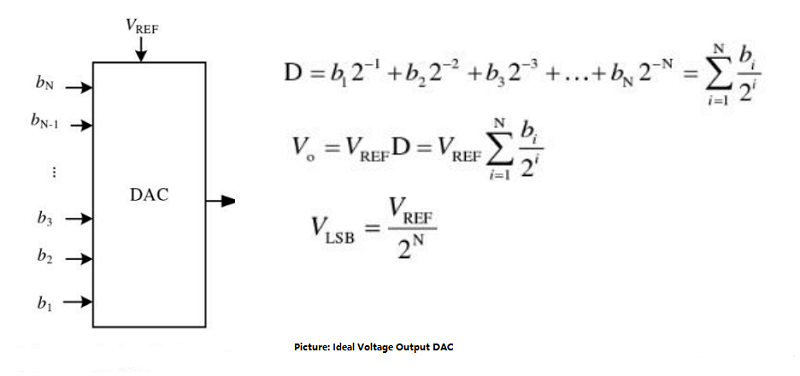
3. Binary Weighting Principle
- An n-bit binary number is represented as D = dₙ₋₁dₙ₋₂…d₁d₀, where MSB (Most Significant Bit) has the highest weight, and LSB (Least Significant Bit) has the lowest.
- Each bit is converted into an analog voltage according to its weight, and the sum of these voltages becomes the final output.
- The output voltage is proportional to the input digital number, with a conversion factor usually denoted as k.

- This equation shows how each bit contributes to the final analog output voltage, making the DAC conversion precise and predictable.
4. Output Resolution and Step Voltage
- The DAC’s output appears as a series of steps, each corresponding to a digital input value.
- More input bits mean smaller step sizes, a smoother output curve, and higher conversion accuracy.
- Example: A 3-bit DAC outputs voltages from 0V to 7V in 8 steps. More bits result in finer steps, making the analog output closer to a continuous signal.
In a nutshell, the working principle of a high-speed DAC board is to convert digital signals into analog signals using a weighted sum of bits, while high-speed optimization and supporting circuits ensure fast, stable, and precise output for demanding applications.
What is the difference between an ADC and a DAC?
ADC (Analog-to-Digital Converter) and DAC (Digital-to-Analog Converter) are two common types of converters in digital signal processing. Their main differences are as follows:
- Function:
An ADC converts a continuous analog signal into its corresponding digital representation, transforming continuous variations in voltage, current, or other analog quantities into discrete digital codes. A DAC, on the other hand, converts digital signals into corresponding analog signals, transforming discrete digital codes into analog voltages or currents. - Direction:
An ADC is an analog-to-digital converter, converting analog signals into digital data. A DAC is a digital-to-analog converter, converting digital data into analog signals. - Input/Output:
The input of an ADC is an analog signal, usually a continuously varying voltage or current, and its output is the corresponding digital code. The input of a DAC is digital data, usually discrete binary codes, and its output is the corresponding analog signal, such as voltage or current. - Applications:
ADCs are widely used for acquiring data from analog sensors (such as temperature sensors, light sensors, etc.), audio signal processing, digital communications, and more. DACs are mainly used in audio signal synthesis, digital audio processing, image generation, and other fields. - Resolution:
Both ADCs and DACs have a performance metric called resolution, which indicates the precision of the numerical representation. For an ADC, resolution represents the number of bits of the digital output. For a DAC, resolution represents the number of bits of the digital input.
To sum up, ADCs and DACs are inverse processes: one converts analog signals into digital signals, while the other converts digital signals back into analog signals. They play crucial roles in signal processing and communication and are often used together in systems where analog signals are converted to digital form, processed digitally, and then converted back to analog.
What are the main types of DAC board?
High-speed DAC (Digital-to-Analog Converter) boards can be categorized based on their architecture and output type:
1. Based on Architecture
- Current-Steering DAC:
This type converts digital signals into analog current outputs by controlling the switch states of multiple current sources. It features high speed (up to GHz) and wide dynamic range, making it suitable for high-frequency applications such as communications and radar. - R-2R Ladder DAC:
This type uses a ladder network of resistors arranged in R and 2R values. It has a simple structure and is easy to integrate, but its speed is relatively lower. It is commonly used in medium- to low-speed, high-precision applications, such as audio processing.
2. Based on Output Type
- Voltage Output DAC:
This DAC directly outputs an analog voltage signal. An external buffer amplifier is usually required to drive the load. It is suitable for applications that demand high voltage stability, such as industrial control. - Current Output DAC:
This DAC outputs an analog current signal, which can be converted to voltage through a load resistor. It offers low output impedance and low power consumption, making it common in high-speed communication and RF systems.
3. Other Special Types
- Σ-Δ (Sigma-Delta) DAC:
By using oversampling and noise shaping, this type achieves high resolution (e.g., 24-bit) and wide dynamic range, though its speed is relatively lower. It is mainly used in audio devices. - PWM (Pulse-Width Modulation) DAC:
This DAC outputs analog signals by modulating the pulse width. It has a simple structure but requires additional filtering. It is often used in motor control and LED dimming applications.
All in all, the core types of high-speed DAC boards include current-steering and R-2R architectures, as well as voltage and current output forms. Choosing the right type requires balancing speed, precision, and power consumption requirements.
How to do High speed DAC design?
Designing high-speed DAC boards requires careful consideration of layout, signal integrity, and electromagnetic interference (EMI) management. The following best practices help optimize performance:
1. Use Multilayer PCBs with Solid Ground and Power Planes
High-speed DACs achieve the best signal integrity on multilayer boards with continuous ground and power planes. Connect exposed pads (EPs) directly to solid ground planes to minimize impedance and noise.
2. Maintain Continuous Inner Ground Planes in Analog Regions
Keep analog sections’ inner ground planes uninterrupted, with minimal gaps. Use staggered vias with small pad diameters to reduce openings. Position solid ground layers beneath key components to stabilize signals.
3. Plan Layer Assignments for Different Signals
Carefully assign input and output signals to specific layers:
- Analog inputs on one layer
- Digital outputs on another
- Clock signals on a dedicated layer
Whenever possible, sandwich each signal layer between two ground planes or use microstrip routing to minimize noise.
4. Pair Power and Ground Layers
Place power layers adjacent to ground planes to reduce inductance and overall noise. If power traces are needed, make them wide enough to minimize voltage drop and inductance.
5. Optimize Ground and Power Connections with Multiple Vias
Use multiple vias (recommended 18mil diameter) for GND and VDD connections. Exposed pads should connect to the same ground plane. For low-inductance grounding, a grid of vias is often used. For example, Maxim recommends a 5×5 matrix (25 vias of 13mil diameter) or at least 12 vias.
6. Minimize Impedance Around Bypass and Critical Capacitors
Keep traces connecting bypass and critical capacitors wide (≥10mil) to reduce impedance and inductance. If components are not above a ground plane, ensure ground traces remain as wide as possible, including thermal pads connected to ground.
7. Use Thermal Pads Strategically
For components with thermal pads, connect each bypass capacitor using two thermal pads, each with a via to ground to reduce inductance. Place capacitors as close as possible to the DAC or ADC to limit parasitic effects.
8. Separate High-Speed Digital Signals from Sensitive Analog Traces
Route high-speed digital signals away from analog lines, clock traces, and other sensitive circuitry to reduce EMI.
9. Keep Signal Traces Short and Avoid 90° Bends
Minimize trace length and avoid sharp corners to reduce reflections and impedance discontinuities.
10. Maintain Symmetry in Differential Networks
Ensure differential analog inputs have a symmetric layout. Keep parasitic networks balanced to maintain signal integrity.
11. Place Bypass Capacitors Close to Components
Surface-mount all bypass capacitors as close as possible to the device, preferably on the same side of the PCB as the DAC or ADC, to reduce inductance.
12. Consider Separate Analog and Digital Power Supplies
Some devices perform better with isolated analog and digital supplies to reduce crosstalk and noise.
13. Use Ground Islands for Isolation
In multi-device designs, use ground “islands” to isolate DAC circuits from neighboring components or other ADC/DAC sections to prevent interference.
What are the applications of high speed DACs?
DACs have a wide range of applications in everyday life and various electronic devices. The main application areas include:
- Audio Equipment
DACs are widely used in audio devices such as speakers, headphones, and MP3 players. They convert digital audio signals into analog audio signals, producing corresponding sound. Thanks to DACs, we can enjoy high-quality music. - Communication Systems
In wireless communication systems, digital signals must be converted into analog signals for transmission. DACs play a key role in devices such as modems and digital walkie-talkies. They convert digital signals into analog signals, which are then sent to the receiver for decoding. - Industrial Control and Instrumentation
DACs are widely applied in industrial automation and measurement instruments. For example, measurement devices often collect data in digital form, but some industrial processes require continuously varying analog signals for control. DACs convert digital data into analog signals, adjusting output voltage to achieve precise control. - Medical Equipment
DACs play a crucial role in medical devices. For instance, electrocardiogram (ECG) machines use DACs to convert digital signals into analog signals to record the heart’s electrical activity. Blood pressure monitors, ventilators, and anesthesia machines also rely on DACs for signal conversion. - Automotive Electronics
Many modern automotive electronic systems, such as in-car audio, navigation systems, and dashboards, use DACs. They convert digital signals into analog signals, which are then amplified and sent to speakers or display panels, providing drivers with audio and visual information.
In closing, DACs are extensively used in audio equipment, communication systems, industrial control, medical devices, and automotive electronics. By converting digital signals into analog form, DACs enhance our audio experience and ensure high-quality communication and control systems in daily life and work.
Where to get Best high speed DAC board?
When looking for high-speed DAC boards, customers are most concerned about several key factors. EBest Circuit (Best Technology) provides professional assurance in all of these areas:
- Industry Experience and Expertise
EBest Circuit (Best Technology) has nearly two decades of extensive experience in high-speed DAC design and manufacturing. We specialize in high-speed signal integrity optimization, EMI management, and high-frequency PCB layout and power management, providing high-performance solutions tailored to customer needs. - Product Stability and Reliability
EBest Circuit (Best Technology) DAC boards undergo rigorous testing. Even under long-term operation, they maintain stable outputs and high-precision performance, making them suitable for industrial, communication, and audio applications. - Technical Support and Engineering Services
EBest Circuit (Best Technology) offers full engineering support, including PCB layout optimization, design advice, and customized solutions. We also provide design references, evaluation boards, and samples to help customers verify performance before purchase. - Customization Capability
EBest Circuit (Best Technology) can customize high-speed DAC boards according to specific customer requirements, including voltage or current outputs, different package types, and optimization for communication, radar, audio, and other applications. - Flexible Supply Options
EBest Circuit (Best Technology) supports both large- and small-volume production, ensuring timely and stable delivery to meet diverse customer demands. - Quality Assurance and Documentation
EBest Circuit (Best Technology) provides complete test reports, product certifications, and a quality assurance system. We have a comprehensive quality management system and holds authoritative certifications, including ISO9001, ISO13485, IATF16949, and AS9100D. These certifications ensure that we meet international standards in design, production, and quality control, delivering reliable high-speed DAC boards to our customers.
To wrap up, a high speed DAC board is not just a piece of hardware—it is the foundation of accurate and high-performance digital-to-analog conversion. If you are interested in the high speed DAC board, pls reach out to EBest Circuit (Best Technology) at sales@bestpcbs.com for the BEST support.
Tags: high speed DAC board