





An OBD tracker connects vehicle location, operating data, and wireless communication in a compact plug-in device. For product developers, fitting these functions into a small enclosure means coordinating the PCB stackup, cellular and GNSS modules, vehicle interface, power supply, and connector assembly. A board that powers up successfully still needs to communicate correctly, enter its intended sleep state, and maintain consistent assembly quality.
EBest Circuit brings PCB manufacturing, component sourcing, assembly, and testing into one engineering-supported service. Our DFM review and BOM optimization support help identify assembly constraints, sourcing issues, and test-access problems before prototype production. With support for samples and small batches, we help engineers evaluate their hardware before scaling the build. Email sales@bestpcbs.com, or visit Contact Us and complete the form at the bottom of the page to discuss your board and request a manufacturing review.
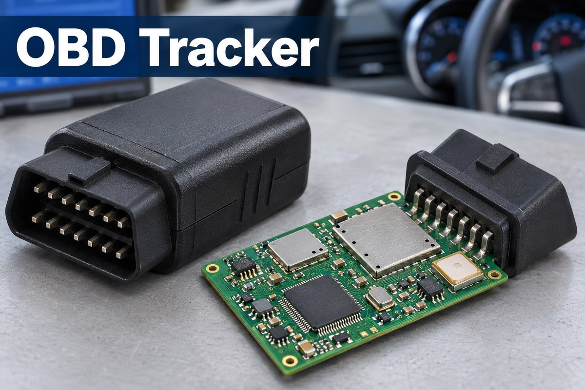
What Is an OBD GPS Tracker and How Does It Work?
An OBD GPS tracker is a compact device that plugs into a vehicle’s OBD-II diagnostic port to draw power and, where supported, read vehicle data. OBD stands for On-Board Diagnostics. A GNSS receiver determines location, while a cellular modem sends records to an app or web platform for vehicle monitoring, trip review, and fleet management.
A direct plug-in design usually avoids a separate power-wiring installation, although vehicle compatibility, port clearance, and device configuration still matter. Location updates, trip history, and alerts depend on the device firmware and tracking platform.
The main functions follow a clear signal path.
- Positioning. The GNSS receiver processes satellite signals to calculate position and time. GPS is one satellite system within GNSS.
- Vehicle communication. Interface circuitry connects the processor to supported vehicle protocols. An OBD connector alone does not guarantee access to every vehicle parameter.
- Processing and storage. The controller combines available readings, applies reporting rules, and may store records when a connection is unavailable.
- Wireless reporting. The cellular module transmits data to the tracking service. Bluetooth, where included, can support local configuration or compatible accessories.
- Power management. The input circuitry supplies the electronics from the vehicle and manages low-power operation when tracking activity is reduced.
A compact rigid multilayer FR-4 PCB can accommodate these functions, with surface-mounted components on both sides and a through-hole connector where the design requires it. Layer count, board thickness, and antenna placement depend on the actual layout and enclosure; there is no single board construction for every tracker.
What Vehicle Data Can OBD2 Fleet Tracking Provide?
OBD2 fleet tracking can combine route information with supported vehicle readings, but these data come from different sources. A location record does not prove that the device is successfully communicating with the vehicle ECU.
- Location and trip history usually come from GNSS and the tracking software.
- Engine speed, vehicle speed, and coolant temperature may be available through supported diagnostic parameters.
- Diagnostic trouble codes can provide fault information when the tracker supports the relevant diagnostic functions.
- VIN, odometer, and fuel information depend on the vehicle, protocol, and device implementation; some require manufacturer-specific support.
- Driving events, such as harsh acceleration, may be calculated using motion sensors, GNSS, vehicle data, or a combination of sources.
- Geofence and unplug alerts, where supported, turn location or power-disconnection events into notifications. Geofencing uses position data and configured boundaries; an unplug alert requires the device to detect the event and retain enough power and connectivity to report it.
For fleet operators, the distinction affects how records are interpreted. Distance estimated from position history is not necessarily the same as an ECU odometer reading. Likewise, an inferred ignition state is different from a directly reported signal.
For PCBA development, this means that a functional test should exercise the intended vehicle communication interface as well as the wireless connection. Supported vehicle data need their own acceptance criteria.
OBD Port GPS Tracker vs. Hardwired Tracker
An OBD port GPS tracker places the vehicle connection directly on the device, while a hardwired tracker uses a cable harness that allows the electronics to sit away from the connection point. This changes enclosure clearance, connector support, and the PCB area needed for external interfaces.
Two reference products illustrate the difference: Teltonika’s FMC003 OBD tracker and FMC920 hardwired tracker. Their specifications are examples of individual designs, not universal limits for either category or specifications of EBest Circuit products.
| Specification | OBD example: FMC003 | Hardwired example: FMC920 |
|---|---|---|
| Device dimensions, L × W × H | 67.2 × 49.6 × 25 mm | 79 × 43 × 12 mm |
| Input supply | 10–30 V DC | 10–30 V DC |
| Backup battery capacity | 170 mAh | 170 mAh |
| Vehicle connection | OBD-II plug-in interface | 5-position cable connection |
| Data and control interfaces | HS CAN, MS CAN, SW CAN, and K-line support | 1 digital input, 1 analog input, and 1 digital output |
The mechanical difference is measurable. In these examples, the OBD device is 11.8 mm shorter but 13 mm thicker. A shorter enclosure therefore does not automatically need less installation clearance. An OBD design must accommodate the connector’s mating direction and insertion loads; a hardwired design must accommodate the cable exit, retention, and strain relief. Device dimensions must not be used as PCB dimensions.
The electrical difference lies in interface requirements. Both examples specify the same 10–30 V input range and 170 mAh battery capacity. Those values do not establish equal runtime or power consumption. The OBD board needs the supported vehicle-bus interface circuitry, while the hardwired example needs circuitry for its three external I/O functions. A harness alone does not provide OBD data access.
For PCB assembly, the OBD format puts particular emphasis on connector position, through-hole soldering where used, and enclosure alignment. The hardwired format shifts attention toward cable attachment and I/O testing. These are different manufacturing tasks, so the test fixture and assembly sequence should follow the actual connection architecture.
Power Protection and Sleep Modes in an OBD Tracking Device
An OBD tracking device must handle a changing vehicle supply and control its current consumption while the vehicle is parked. Nominal battery voltage is only one part of the operating environment.
Input protection and regulation
Vehicle electronics can encounter voltage dips during cranking and electrical transients during operation. The power design may therefore need transient suppression, input filtering, reverse-polarity protection, and a regulator selected for the intended operating range. The required protection depends on the vehicle application and qualification plan.
At assembly level, polarity, component ratings, and approved substitutions matter. Replacing a protection component with a physically similar part can change the circuit’s behavior even when the footprint matches.
Sleep and wake behavior
A tracker may reduce consumption by turning off its GNSS receiver, limiting cellular activity, or placing other circuits in standby. Deeper sleep can reduce responsiveness or require additional time to reconnect. Wake conditions can include movement, a timer, or supported vehicle signals.
The useful measurement is the current drawn by the complete device in its defined state. Regulator consumption, interface circuits, indicators, and communication activity can all affect the result. Firmware that repeatedly wakes the device—or keeps the vehicle network active—can undermine the intended saving.
Production testing can verify specified operating and sleep currents. Automotive transient and environmental qualification are separate activities with their own test conditions.
EBest Circuit’s PCB Manufacturing and Assembly Capabilities for OBD Trackers
EBest Circuit supports compact OBD tracker builds with standard PCB processes covering 1–10 layers, 4/4 mil line width and spacing at 1 oz copper, and SMT placement down to 01005 components. These capabilities provide concrete options for fitting communication modules, power circuits, and supporting components onto a small board.
| Manufacturing parameter | Capability and applicable condition |
|---|---|
| PCB layer count | 1–10 layers in the standard process range; higher-layer builds receive special-process review |
| Thin 4-layer construction | Minimum standard finished thickness of 0.6 ± 0.1 mm, with a maximum individual board size of 350 × 400 mm at that construction |
| Line width / spacing | 4/4 mil, approximately 0.102/0.102 mm, for 1 oz inner and outer copper |
| Finished hole diameter | 0.20 mm standard minimum; 0.15 mm under special-process review |
| ENIG finish | Nickel 3–8 μm; gold 0.025–0.125 μm |
| Minimum SMD component | 01005 |
| Minimum BGA pitch | 0.25 mm |
| Assembly methods | SMT, THT, and mixed assembly |
These values are manufacturing capabilities, not a requirement to design at every minimum. Copper weight, layer count, hole structure, component package, and panel support are reviewed together before the process is released.
Assembly capacity and schedule
- Placement capacity — 13.2 million components per day. Finished-board output varies with component count, assembly steps, inspection, and functional testing.
- Assembly lead time — 1–5 days for eligible projects. Scheduling is confirmed once PCBs and components are ready and production and test requirements are agreed.
- Separate project stages. PCB fabrication, component sourcing, test-fixture preparation, and shipping have their own schedules.
How Is an OBD2 GPS Tracker PCBA Tested?
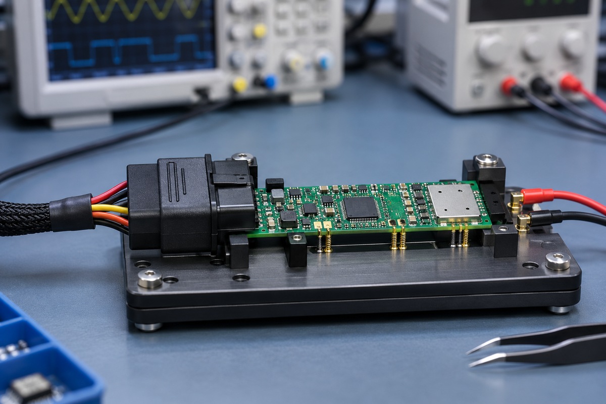
An OBD2 GPS tracker PCBA needs inspection and electrical testing because neither one alone verifies the complete assembly. The test sequence should separate soldering defects, power faults, communication failures, and configuration problems.
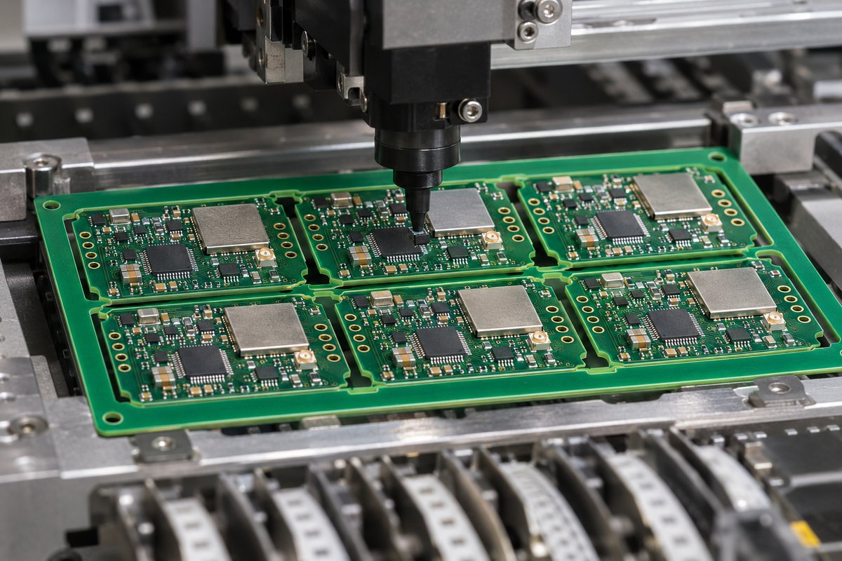
- Inspect the assembly. AOI checks visible placement and soldering features. X-ray inspection can examine joints beneath packages such as LGA modules, where optical access is limited.
- Verify the power circuits. Initial checks cover shorts, supply rails, polarity, and current draw under controlled conditions before normal operation.
- Load and identify the firmware. Where programming is included, the board receives the approved firmware and configuration, with the required identity records associated with the unit.
- Exercise communication functions. The test plan can include cellular registration and data transfer, GNSS reception under defined conditions, and Bluetooth communication where fitted.
- Test the vehicle interface. An agreed simulator or representative vehicle setup exercises the supported communication functions and selected data responses.
- Measure sleep and recovery. The configured board enters its intended low-power state, meets the specified current limit, and responds to the defined wake event. If unplug alerts are part of the product, the agreed test can also verify backup-power switchover and event reporting after external power is removed.
A successful GNSS fix in production is a functional check, not a complete measurement of positioning performance in every installation. Similarly, cellular registration does not by itself confirm that the tracker has transmitted a valid record to its destination. Separating these tests makes failures easier to diagnose.
Case Study of a 4G OBD Tracker PCB Assembly
This manufacturing-planning case concerns an OBD-II plug-in 4G LTE GPS/GNSS tracker submitted to EBest Circuit for a turnkey quotation and DFM review. The following specifications describe the requested build and proposed manufacturing approach.
Application
The product combines cellular reporting, satellite positioning, Bluetooth, and a controller on a compact board for vehicle tracking. Its requested production scope covers PCB fabrication, component sourcing, double-sided SMT, a through-hole connector, and testing.
| Project item | Requested specification |
|---|---|
| PCB construction | 4-layer high-Tg FR-4 |
| Board size | 46 × 31 mm |
| Finished thickness | 1.0 mm |
| Surface finish | ENIG |
| Controlled impedance | 50 Ω single-ended and 90 Ω differential, on designated nets |
| Assembly | Double-sided SMT and one THT connector |
| BOM | Approximately 68 line items |
| Functional blocks | LTE, GNSS, BLE, and MCU circuitry |
| Inspection requirement | 100% AOI and X-ray inspection of LGA joints |
| Initial engineering validation | LTE network attachment, GNSS fix, and BLE operation |
| Supply arrangement | Customer-supplied eSIM and battery pack; substitutions require approval |
Challenge
Three manufacturing issues stand out. First, the small double-sided board must accommodate radio modules, power circuitry, and test access without compromising connector clearance. Second, the LGA joints cannot be assessed adequately by optical inspection alone. Third, customer-supplied parts and restricted substitutions must remain aligned with the approved BOM and hardware revision.
Solution
The proposed approach starts with a combined PCB and assembly review. Stackup and impedance requirements are matched to the fabrication data, while the panel arrangement, soldering sequence, and connector support are considered together.
The inspection plan pairs AOI with LGA X-ray inspection. Engineering samples then exercise LTE attachment, GNSS reception, and BLE operation before the production test process is finalized. Any vehicle-data tests are defined separately against the intended protocol and firmware.
BOM control keeps customer-supplied items identifiable and routes alternative-part proposals for approval before use. This prevents an availability-driven substitution from silently changing the radio, power, or mechanical configuration.
Customer Benefit
The planned approach gives the engineering team a route from compact-board review to inspectable, testable samples. It is intended to expose assembly constraints early, distinguish hidden-joint defects from functional problems, and preserve configuration consistency as the design moves toward repeat production.
Why Choose EBest Circuit for OBD Tracker PCB Assembly?
EBest Circuit combines PCB and PCBA manufacturing with engineering support, sourcing, and inspection. For a compact vehicle tracker, this connects the physical board, its components, and its test requirements within one manufacturing workflow.
- Engineering support before the build. Our DFM review and BOM optimization support address production issues while changes are still easier to make. Connector clearances, difficult solder joints, test access, and sourcing constraints receive attention alongside the board specification.
- PCB and PCBA factories under coordinated management. Fabrication and assembly teams can resolve stackup, panelization, and soldering questions together. Customers have fewer supplier handoffs when a board-level issue affects the assembly process.
- Relevant quality systems. Our quality management certifications include ISO 9001, ISO 13485, IATF 16949, and AS9100D. For automotive electronics, IATF 16949 is particularly relevant to process discipline and traceability. These are management-system credentials; product-specific qualification remains tied to the agreed program.
- Flexible sourcing with controlled changes. Full turnkey, partial turnkey, and consignment options accommodate radio modules and customer-controlled parts. Proposed alternatives are reviewed against the design instead of being selected on footprint alone.
- Samples, small batches, and traceable repeat builds. Prototype support helps engineers evaluate the assembled board, while material and batch traceability support investigation and configuration control as production develops.
The value is practical coordination: the same project requirements guide the board build, component supply, assembly, and agreed tests.
OBD Car Tracker FAQs
Does a 4G OBD tracker need a SIM card?
A cellular tracker needs a suitable mobile-network subscription and supported network access. Depending on the design, it may use a removable SIM or an embedded SIM solution. Network bands, provisioning, and modem support must match the deployment region.
Can an OBD tracker keep recording without mobile coverage?
It can if the hardware and firmware support local storage. Stored records may be uploaded when connectivity returns. This does not provide live remote updates during the outage.
Is an OBD tracker the same as an OBD scanner?
No. A tracker focuses on ongoing location and operating records, while a scanner focuses on diagnostic interaction. Their functions can overlap, but a tracking device does not automatically provide the service functions of a diagnostic tool.
Can the same tracker be used on a 12 V car and a 24 V truck?
Only if its input circuitry, protection, connector arrangement, and communication support are designed for both applications. A matching connector or the label “OBD” is not enough to establish compatibility.
Does an OBD tracker need a backup battery?
Not always. A backup battery can support limited operation after vehicle power is removed, depending on the design. It also adds charging, protection, space, and temperature considerations; operating time depends on battery capacity and the active functions.
How often does an OBD tracker update its location?
The interval depends on firmware settings, the service configuration, and network availability. Some products vary reporting by time, distance, or vehicle activity. More frequent updates can increase communication activity and energy use, so the intended reporting profile should be included in functional and power testing.
What affects the cost of an OBD tracker PCBA?
Radio modules and other BOM items, board construction, assembly complexity, quantity, and test coverage all contribute. Fixtures, programming setup, and engineering samples can add one-time costs. Separating these from recurring unit costs makes prototype and production quotations easier to compare.
Bring your OBD tracker project to EBest Circuit for coordinated PCB fabrication, component sourcing, assembly, and testing. Our own PCB and PCBA factories, engineering review, quality management systems, and material and batch traceability help connect prototype findings with controlled repeat builds. You gain a manufacturing team that can address board construction, component changes, and assembly requirements together. Visit Contact Us, scroll to the bottom of the page, and complete the form to request a quotation and discuss your manufacturing requirements.
You may also like
Tags: 4G GPS Tracker, OBD tracker, OBD Tracker PCB