





To determine value of a shorted SMD capacitor, first confirm the failed component and preserve the evidence before removal. Because a hard-shorted capacitor can no longer reveal its original capacitance, recover the intended value from the schematic, BOM, boardview, a known-good board, a repeated circuit, or the IC manufacturer’s reference design.
Package size and board location narrow the possibilities but cannot identify capacitance by themselves. A visually identical part may have a different value, voltage rating, dielectric, tolerance, or function. The method below shows how to determine value of a shorted SMD capacitor without turning an uncertain guess into a second failure.

Can You Determine Value of a Shorted SMD Capacitor by Direct Measurement?
A hard-shorted capacitor cannot provide a valid capacitance reading. A capacitance or LCR meter applies a small test signal and observes the device’s response. When the dielectric has broken down and the terminals are connected by a low-resistance path, the instrument sees leakage or resistance instead of normal charge storage.
An in-circuit reading creates another problem: every component connected to the same net can affect the result. Semiconductor junctions, other capacitors, resistive loads, transformers, inductors, and internal IC paths may all sit between the probes. A continuity beep or a near-zero resistance reading therefore proves only that the rail has a low-resistance path. It does not identify the failed part or reveal the capacitor’s original value.
If the removed part no longer appears shorted after cooling, treat any capacitance reading as supporting evidence rather than proof. Heat and released board strain can temporarily change a marginal MLCC fault.
How Do You Confirm the SMD Capacitor Is Shorted Rather Than Another Parallel Component?
Confirm the faulty component by isolating the low-resistance rail and proving that the short disappears when the suspect part is removed. Treat the first meter reading as a symptom, not a verdict.
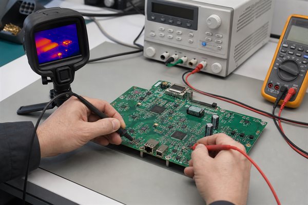
- Step 1: Isolate and verify power removal. Disconnect the external supply, batteries, cables, and any backup source. Discharge stored energy by the product’s approved procedure, then confirm with a meter that the rail is no longer energized before using resistance or continuity mode. Do not work on mains, high-voltage, or large-capacitor sections without the specified discharge equipment and safety procedure.
- Step 2: Inspect the rail before measuring. Under magnification, examine the suspect capacitor and nearby components for cracks, chipped corners, discoloration, corrosion, solder bridges, conductive debris, damaged vias, and disturbed joints. Record the reference designator and photograph the area before cleaning because visible evidence may help identify whether the capacitor failed from flex, impact, contamination, overheating, or an upstream electrical fault.
- Step 3: Measure resistance in both probe polarities. Set the multimeter to resistance mode rather than relying only on the continuity buzzer. Measure between the rail and ground, reverse the probes, and allow several seconds for the reading to settle. A reading that starts low and rises may be normal capacitor charging; a stable near-zero reading in both directions is stronger evidence of a short, but it still does not identify which parallel component has failed.
- Step 4: Compare equivalent points. Repeat the measurement with the same meter range, probe polarity, settling time, and power-off condition on a known-good board or an electrically identical channel. Confirm that the board revision, circuit option, IC population, and rail function match before using the comparison. Large differences help prioritize the suspect rail, while similar low readings may indicate that the circuit normally has low resistance.
- Step 5: Localize the heat under controlled limits. Use current injection only after identifying the rail’s normal voltage and the safe limits of every connected device. Start below the rail voltage with a conservative current limit, monitor total current, and use a thermal camera, freeze spray, or another controlled indicator to locate the first component that warms. Stop immediately if an IC, trace, connector, or unknown part heats rapidly, and never increase voltage or current merely because the fault is difficult to find.
- Step 6: Isolate and cross-check the suspect component. Remove the capacitor with a controlled rework process, or lift one terminal when the package and board permit it without pad damage. Measure the removed component and the two board pads separately after they cool. The diagnosis is confirmed when the capacitor remains low resistance while the board-side short disappears; if the pads remain shorted, the failed part is elsewhere on the shared rail and further isolation is required.
Do not apply an arbitrary bench-supply voltage to an unknown rail. The permitted voltage and current depend on the rail’s normal operating level, downstream IC limits, copper capacity, and the diagnostic method. If those limits are not known, trace the circuit or obtain design information before injection. A shorted IC, TVS diode, MOSFET, connector contamination, or solder bridge can heat near a capacitor and create a false conclusion.
What Should You Record Before Removing the Suspect SMD Capacitor?
Photograph and document the component before heat, cleaning, or removal changes the evidence. This record makes later value recovery and repair verification much more reliable.
- Reference designator: Record the silkscreen identifier, such as C124, and any nearby IC or connector designators.
- Board identity: Capture the PCB part number, assembly number, revision, variant, and serial or lot information when applicable.
- Exact location: Take one close image and one wider image showing orientation, nearby parts, vias, and copper areas.
- Package dimensions: Measure length and width with suitable magnification rather than estimating 0402, 0603, or 0805 by eye.
- Electrical evidence: Record resistance to ground, probe polarity, meter range, rail name, and comparison readings from a good channel or board.
- Physical condition: Note cracks, discoloration, lifted terminations, solder condition, contamination, or signs of flex damage.
Keep the removed part in a labeled container. Do not mix it with neighboring capacitors removed during fault isolation. If the component breaks during removal, retain the fragments because termination style and construction can still support identification.
How Can Schematics, BOMs and Boardviews Reveal the Original Capacitor Value?
The released schematic and BOM are normally the highest-confidence sources for the original value. Use the reference designator to connect the physical component to its circuit record, then verify that every document matches the exact board revision and assembly variant.
| Evidence source | Confidence | What it can confirm | Main limitation |
| Released BOM and schematic | Highest | Capacitance, voltage, tolerance, dielectric, package, and approved MPN | Must match the manufactured revision and variant |
| Boardview or CAD database | High | Reference designator, net, footprint, placement, and circuit relationship | May omit purchasing specifications or approved alternates |
| Known-good identical board | High when controlled | Installed package and measurable out-of-circuit value | Must be the same revision, option, and population variant |
| Repeated circuit on the same board | Moderate to high | Likely matching value and function | Channels may use different compensation or option values |
| IC datasheet or reference design | Moderate | Expected value range and required capacitor characteristics | The production design may intentionally differ |
| Package size and location | Low | Plausible capacitance and voltage families | Cannot uniquely identify the original component |
Start with the BOM’s manufacturer part number when available. A full MPN can reveal more than nominal capacitance: rated voltage, capacitance tolerance, dielectric class, package, temperature range, termination, and qualification grade. Check change notices, approved vendor lists, deviation records, and assembly option notes because the as-built part may differ from an early schematic value.
How Can a Donor Board or Repeated Circuit Help Identify the Capacitor Value?
A revision-matched donor board or an electrically identical repeated circuit can identify the missing value by providing a known-good capacitor in the same circuit position. Locate the matching reference designator or trace the same IC pins, power rail, ground return, and neighboring components. Before using it as evidence, confirm that the board revision, assembly variant, fitted IC, option resistors, and surrounding component population match the faulty circuit.
For a donor board, photograph the known-good component and record its package dimensions and location. If the repair procedure permits removal, measure the matching part out of circuit using the controlled LCR process described below. Use the result to identify the likely nominal capacitance, then confirm voltage rating, tolerance, dielectric, and other specifications from the donor BOM, schematic, approved part number, or manufacturer data.
A repeated circuit on the same PCB can be used in the same way when both channels are electrically equivalent. This is common in motor phases, communication ports, memory lanes, regulator phases, and repeated sensor inputs. Trace both capacitor pads and compare their connections rather than relying on visual symmetry. Similar-looking channels may use different values for compensation, startup timing, filtering, or EMC tuning, so the corresponding component becomes reliable evidence only after the net connections and circuit function match.
If removing a working donor component is not acceptable, use it only to confirm placement, package, and circuit relationship, then recover the exact value from its associated BOM or schematic. Do not treat an in-circuit capacitance reading as the final value because parallel capacitors, semiconductor paths, and other connected components can distort the measurement.
How Can Circuit Function, Package Size and Board Location Narrow the Value?
Circuit function can narrow the capacitor to a realistic value range; package size and board location provide supporting limits. Trace both pads and identify the connected pins, rail, and surrounding topology before selecting candidates.
| Likely function | Location clue | Parameters that matter | Why guessing is risky |
| IC decoupling | Very close to a power pin and ground return | Capacitance under DC bias, voltage, dielectric, package, ESL | Too little effective capacitance can raise supply noise |
| Bulk rail support | Near a regulator, connector, or load cluster | Capacitance, voltage, ripple current, ESR, temperature | Wrong ESR or ripple capability can cause heating or instability |
| Switching regulator control | Connected to feedback, compensation, bootstrap, or soft-start pins | Exact value, tolerance, dielectric, leakage, voltage | A small change can alter loop response, timing, or switch stress |
| Signal coupling or filtering | In series with or shunting a signal path | Value, dielectric, tolerance, loss, voltage | Wrong value changes cutoff frequency or signal integrity |
| Safety or surge suppression | Across an isolation boundary, mains input, or protected interface | Safety class, impulse rating, technology, spacing | A same-size general capacitor may be unsafe |
An 0603 footprint can hold many capacitance and voltage combinations. For Class II MLCCs such as X5R or X7R, the effective capacitance may fall substantially under applied DC voltage, especially in small packages. Package identification therefore cannot substitute for the application requirements or approved component data.
How Should You Measure a Matching SMD Capacitor With an LCR Meter?
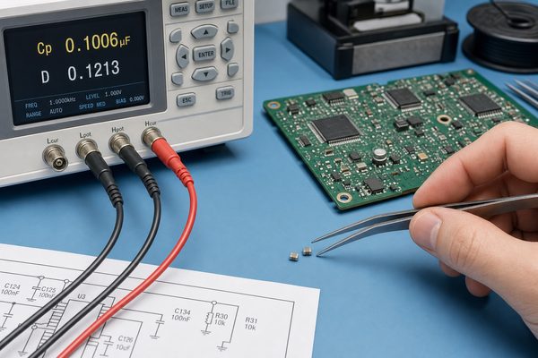
Measure a known-good matching capacitor out of circuit with controlled test settings and proper fixture compensation. A basic capacitance reading is useful, but an LCR meter provides better control over frequency, signal level, and equivalent circuit assumptions.
- Step 1: Prove that the comparison component is equivalent. Confirm that the donor board has the same PCB revision, assembly variant, IC version, option population, and circuit function as the faulty board. Match the reference designator when available; otherwise trace both capacitor terminals and verify that they connect to the same IC pins, rail, ground return, and surrounding network. Do not use a visually similar component from another channel until electrical equivalence is established.
- Step 2: Remove the donor capacitor without changing its condition. Record its location and orientation, support the PCB, and use the approved temperature-controlled rework process for that package. Heat both terminations evenly and lift the part without twisting, pressing, or bending the board. Reject the test sample if the body chips, a termination separates, or excessive heat or mechanical force may have damaged the MLCC.
- Step 3: Let the component stabilize and clean it. Place the removed part on a clean, nonconductive surface and allow it to return to room temperature before measurement. Remove flux with a compatible electronics cleaner and inspect the terminations for solder bridges, residue, cracks, or handling damage. Moisture, contamination, residual heat, and probe pressure can change a small-capacitance or high-impedance reading.
- Step 4: Prepare and compensate the LCR fixture. Select an SMD tweezer fixture or short test fixture suitable for the component size, then perform the instrument’s open compensation with the contacts separated. Perform short compensation with the contacts joined in the same physical position used for measurement. Repeat compensation if the fixture position, cable, range, frequency, or test setup changes, and stop if the instrument reports an unstable or failed compensation.
- Step 5: Use the correct measurement conditions. Select capacitance as the primary parameter and use the manufacturer’s specified test frequency, signal level, and equivalent-circuit mode when the MPN or capacitor family is known. If those conditions are unknown, measure at more than one appropriate frequency and record every setting instead of treating one default reading as authoritative. Keep contact pressure light and consistent, and remember that a zero-bias LCR reading does not reproduce the capacitance of a Class II MLCC under operating DC voltage.
- Step 6: Confirm repeatability and interpret the result. Take at least three readings, removing and reseating the component between measurements; reverse it in the fixture when practical to expose contact-related variation. A credible result should stabilize and remain reasonably consistent after fixture uncertainty and component tolerance are considered. Use the measured value to identify the likely nominal capacitance, then verify voltage rating, dielectric, tolerance, package, DC-bias performance, temperature behavior, and aging from the BOM or manufacturer data. If readings drift widely or the original test conditions cannot be established, classify the value as unconfirmed rather than approving a replacement from that measurement alone.
How Do You Choose a Safe Replacement for a Shorted SMD Capacitor?
Match the electrical function and all critical ratings, not only the nominal capacitance. The safest replacement is the approved manufacturer part number or a documented alternate validated for the same circuit and assembly process.
- Capacitance: Match the specified nominal value and ensure the effective value remains adequate under operating bias and temperature.
- Voltage rating: Use a rating at least as high as the approved design value, while checking that a higher rating still fits and provides the required effective capacitance.
- Dielectric: Preserve the required stability, loss, temperature range, and aging behavior. Do not replace C0G or NP0 timing parts with X5R or X7R merely because the nominal value matches.
- Tolerance: Keep the specified tolerance where it affects filters, timing, compensation, sensing, or impedance.
- Package and termination: Match the land pattern, component height, solderability, mechanical stress, and assembly profile.
- Polarity: Confirm orientation for tantalum, aluminum, polymer, and other polarized chip capacitors. Most ceramic MLCCs are nonpolarized.
- ESR and ripple capability: Check these for regulator outputs, bulk storage, pulsed loads, and circuits in which ESR contributes to stability.
- Safety or qualification: Preserve required safety class, surge rating, temperature grade, and application qualification when those are part of the design.
When Is an Equivalent Capacitor Value Acceptable and When Is Guessing Unsafe?
Use an equivalent only when the circuit function is known and every critical replacement parameter stays within the approved design limits. Matching the footprint or obtaining one capacitance reading is not enough.
| Situation | Decision | What must be confirmed |
| Approved MPN or documented alternate is available | Normally acceptable | Correct board revision, package, polarity, and approved sourcing status |
| Ordinary local decoupling with a fully understood rail | May be acceptable after verification | Nominal and effective capacitance, voltage rating, dielectric, tolerance, package, temperature range, and transient demand |
| Regulator input or output filtering | Requires circuit-level review | Effective capacitance under DC bias, ESR, ripple-current capability, regulator stability requirements, and startup behavior |
| Feedback, compensation, timing, resonant, RF, snubber, bootstrap, charge-pump, or precision-filter circuit | Do not substitute by guess | Exact function plus tolerance, ESR, ESL, leakage, loss, voltage coefficient, and frequency behavior |
| High-voltage, surge, mains-connected, isolation, or safety-related position | Use only an approved specification | Safety class, rated and impulse voltage, capacitor technology, creepage or clearance implications, and applicable qualification |
| Original value or circuit function cannot be confirmed | Stop before installation | Obtain reliable documentation or complete a controlled engineering validation |
Guessing is unsafe when the wrong capacitor could alter control-loop stability, timing, signal integrity, electrical safety, or component stress. In these positions, a candidate part must be supported by the schematic, BOM, approved manufacturer data, or a documented validation using simulation and instrumented prototype testing.
If the evidence remains incomplete, record the uncertainty and do not release the board as repaired. A temporary candidate used during controlled diagnosis is not automatically an approved production replacement.
How Do You Install and Verify the Replacement Without Causing Another Failure?
Repair is complete only after the root cause is addressed and the board passes controlled electrical and functional checks. A capacitor may have failed because of board flex, overvoltage, reverse polarity, excessive ripple, thermal stress, contamination, or damage elsewhere on the rail.
- Step 1: Prepare and inspect the pads. Remove loose solder and flux with the approved rework materials, taking care not to scrape the solder mask or pull the copper. Under magnification, check that both pads remain flat and firmly attached, the connected vias are intact, and no copper has lifted. Stop the repair if a pad moves, a via barrel appears damaged, or the land no longer provides enough area for a reliable joint.
- Step 2: Confirm that the short is gone. After the board and pads cool, measure resistance between the rail and ground using the same meter range, probe polarity, and settling time recorded before removal. The reading should change consistently with removal of the failed capacitor and should not remain at the previous stable near-zero value. If the rail is still shorted, do not install a replacement; continue isolating other capacitors, ICs, protection devices, solder bridges, and contaminated areas on the shared net.
- Step 3: Position and solder the approved replacement. Verify the part number, package, capacitance, voltage rating, dielectric, and polarity before rework begins. Align the component centrally on both pads, use only enough solder to form controlled fillets, and follow the approved temperature profile or rework procedure. Heat both terminations evenly and avoid pressing, twisting, or cooling the MLCC abruptly because thermal and mechanical stress can crack the ceramic body.
- Step 4: Inspect the completed joint. Under magnification, confirm that the component is flat, centered, and connected at both terminations with smooth, properly wetted joints. Look for bridges, solder balls, incomplete wetting, excessive solder, tombstoning, cracked corners, displaced neighboring parts, pad lifting, and conductive residue. Rework any visible defect before power is applied, and replace the capacitor if its body was chipped or stressed during installation.
- Step 5: Apply power under controlled limits. When the product procedure permits, set a current-limited supply to the known rail or input voltage and begin with a conservative current limit based on the normal startup demand. Monitor input current, rail voltage, regulator behavior, and component temperature as power is introduced. Disconnect power immediately if current reaches the limit unexpectedly, the rail collapses, the replacement heats rapidly, smoke or odor appears, or another component becomes the first hot spot.
- Step 6: Verify operation through realistic conditions. Check startup first, then confirm the repaired rail at idle, normal load, and the applicable transient or functional load. Observe rail voltage, ripple or noise when relevant, input current, temperature rise, and the function controlled by that circuit. Compare the results with the product specification or a known-good unit, and do not release a board that passes only at idle but fails during load changes or warm operation.
- Step 7: Complete the repair record and release decision. After the board has operated and cooled, repeat the resistance and visual checks to confirm that the fault has not returned. Record the removed component, replacement MPN and lot, board revision, measured resistance, voltage, current, temperature observations, test conditions, and final functional result. Release the board only when every required check passes; otherwise record the unresolved symptom and return it for further diagnosis.
What Capacitor Details Should Be Recorded in the BOM After Repair?
Record enough information to reproduce the approved repair without repeating the investigation. A BOM entry that says only “0.1 µF capacitor” is incomplete for controlled production or long-term service.
- Identification: Reference designator, internal part number, manufacturer, full MPN, and approved alternates.
- Electrical specification: Nominal capacitance, tolerance, rated voltage, dielectric or capacitor technology, ESR or ripple requirement when applicable.
- Mechanical specification: Package code, metric dimensions, height limit, termination type, and polarity marking when applicable.
- Application controls: Temperature grade, safety class, qualification requirement, and any no-substitution note.
- Traceability: Board revision, assembly variant, engineering change reference, approver, date, and verification results.
Update the controlled BOM and repair instruction rather than leaving the value only in a technician’s notes. If an alternate is approved, state the reason and the parameter comparison that supports equivalence. This prevents later procurement substitutions from silently changing circuit behavior.
FAQs About Determining the Value of a Shorted SMD Capacitor
Q1: Can a cracked MLCC fail intermittently instead of staying shorted?
A1: Yes, a crack can create an intermittent fault. Board flex, temperature change, vibration, or probe pressure may open and close a damaged internal electrode or termination. Record resistance while gently controlling temperature or mechanical stress, but do not flex a powered board unless the approved diagnostic procedure permits it.
Q2: Can a board be powered temporarily after a shorted decoupling capacitor is removed?
A2: Only as a controlled diagnostic step. Removing one capacitor may allow startup, but it can reduce local decoupling, increase supply noise, or disturb a high-speed return path. Use current-limited power, avoid full-load qualification, and install the approved replacement before release.
Q3: Should every capacitor in a parallel bank be replaced after one fails?
A3: Not automatically. Replace other parts only when evidence shows shared overstress, heat, contamination, age-related degradation, or an approved maintenance rule. MLCC banks do not require blanket replacement merely because one component cracked.
Q4: Can the color of an unmarked MLCC reveal its capacitance?
A4: No, body color is not a dependable value code. Ceramic formulation, coating, firing process, and manufacturer choices can produce similar colors across many capacitance and voltage combinations. Use the circuit location, documentation, or a verified comparison part instead.
Q5: Can soft-termination MLCCs reduce repeat cracking?
A5: They can improve resistance to board-flex stress. A flexible termination absorbs some strain between the ceramic body and PCB, but it does not correct poor component placement, excessive depaneling force, mounting-screw distortion, or an unsuitable footprint.
Q6: Can a tiny shorted MLCC damage a PCB trace or copper plane?
A6: Yes, package size does not limit fault current. A low-impedance supply can drive enough current through a small MLCC to overheat pads, vias, traces, or nearby laminate. Inspect the surrounding copper before fitting a replacement, especially when the failed part is discolored or charred.
Q7: Can a faulty MLCC behave like a resistor instead of a complete short?
A7: A damaged dielectric can create measurable leakage or resistive behavior. The reading may change with temperature, voltage, or time and may not trigger a continuity buzzer. Compare resistance under controlled conditions and isolate the part before deciding whether the rail itself is at fault.
Q8: Is a smaller MLCC package less likely to crack near a board edge or screw?
A8: Package size alone does not remove the risk. Smaller parts may experience less differential strain, but placement direction, distance from edges and fasteners, land geometry, PCB thickness, and assembly force also matter. Correct the mechanical cause before approving a size change.
Q9: Why can heating an MLCC change its measured capacitance?
A9: Heat can reset part of the aging behavior of Class II ceramic dielectrics. The measured value may rise after rework and then decrease as the component ages again. Allow the part to stabilize and compare it with the manufacturer’s specified test conditions rather than treating a hot reading as nominal.
Q10: Does a physically larger MLCC automatically make a safer replacement?
A10: No, a larger package is not automatically better. It may retain more capacitance under DC bias, but it can also change land compatibility, placement clearance, parasitic behavior, and board-flex stress. Approve the package change only after checking both electrical performance and assembly risk.
Conclusion
A failed shorted part cannot tell you what its capacitance used to be. To determine value of a shorted SMD capacitor, first prove that the component—not another device on the same rail—caused the fault. Recover the specification from revision-matched records or a verified comparison circuit, then check capacitance, voltage rating, dielectric, tolerance, package, ESR, polarity, and operating conditions before installing the replacement.
Need help turning a repair finding into a controlled production change? Send your Gerber or ODB++, NC drill files, BOM, board revision, stackup, quantity, assembly details, firmware or programming requirements, test plan, and required quality documentation to sales@bestpcbs.com. EBest Circuit can review the component substitution, assembly implications, and test requirements and then prepare a quotation.
You may also like


Tags: shorted SMD capacitor value, SMD capacitor replacement, SMD capacitor short testing, unmarked SMD capacitor identification