

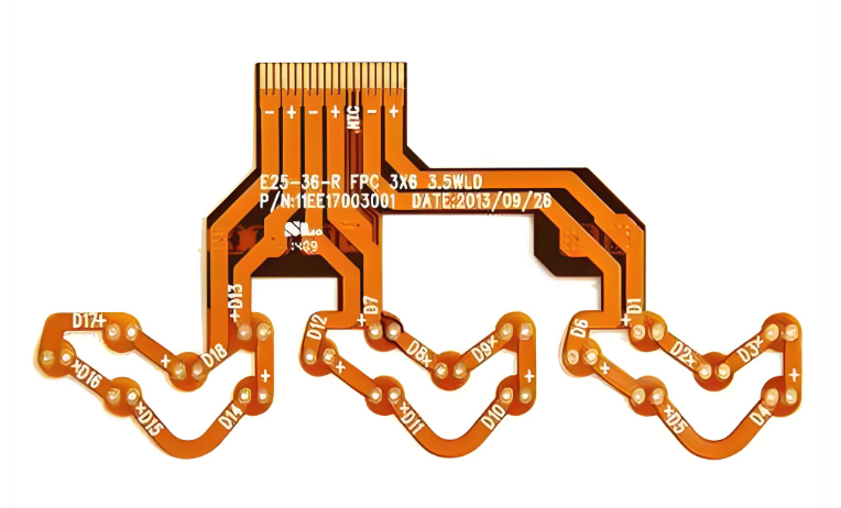
What is Flex PCB Assembly?
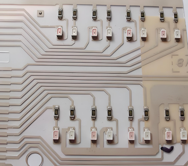
Flex PCB assembly is the process of mounting electronic components onto flexible substrates, such as polyimide or PEEK, rather than traditional rigid boards. This technology allows the circuitry to bend, fold, or twist, making it essential for compact, high-performance electronics where space and weight are critical constraints.
Unlike rigid boards, flex assemblies often eliminate the need for bulky connectors and cables by integrating the wiring directly into the circuit design.
Quick-Quote Flex PCB Assembly
Why EBest Circuit is Trusted China Flex PCB Assembly Manufacturer?
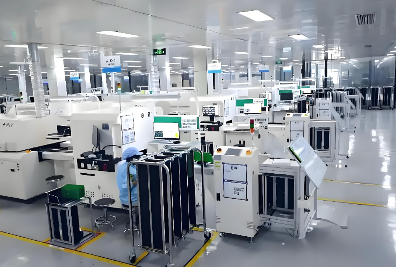
Choosing a reliable manufacturing partner is critical for flex PCB assembly, because flexible materials require more precise handling and process control than standard rigid boards. EBest Circuit (Best Technology) has built strong trust among global customers through consistent quality and engineering expertise.
Founded in 2006, EBest provides one-stop PCB and PCBA solutions, covering design, prototyping, and mass production. With over 20 years of experience, the company supports a wide range of PCB types, including flexible and rigid-flex designs.
Key advantages include:
- Full-process service from PCB fabrication to assembly
- Strong experience in flex and rigid-flex PCB manufacturing
- Certified quality system (ISO9001, ISO13485, IATF16949, AS9100D)
- Fast turnaround, including urgent delivery support
- Dedicated engineering team for DFM and BOM optimization
As a result, customers can rely on EBest for stable quality, fast delivery, and professional technical support in flex PCB assembly projects.
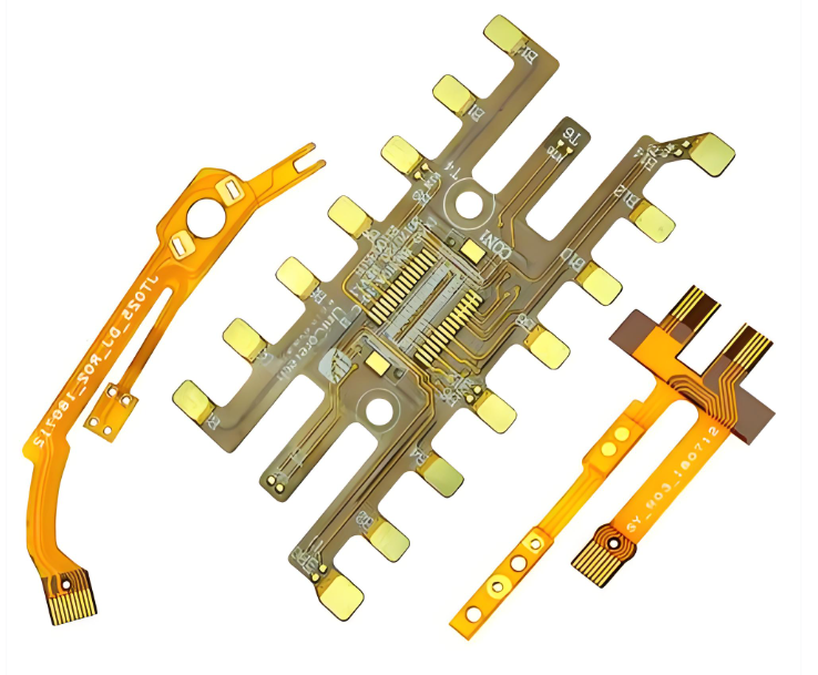
What Flex PCB Assembly Services and Certifications Do We Offer?
Flex PCB assembly requires specialized services that go beyond standard SMT processes, and EBest provides a comprehensive range of capabilities to meet different application needs.
Our services include:
- Flexible PCB fabrication (single-sided, double-sided, multilayer, rigid-flex)
- SMT and THT assembly for flexible substrates
- Component sourcing with verified supply chain
- Functional testing and reliability validation
- Box build and system integration
In addition, EBest maintains strict quality standards through multiple certifications, ensuring that every project meets international requirements. These certifications including:
- ISO9001
- ISO13485 (for medical devices)
- IATF16949 (for automotives)
- AS9100D (for aerospace applications)
- UL
- REACH
- RoHS
Flex PCB Assembly Process – Step by Step
The flex PCB assembly process requires tighter control than standard PCB assembly, because flexible substrates are sensitive to both heat and mechanical stress. Therefore, each stage must be carefully optimized to avoid deformation, misalignment, or reliability issues during production.
Below is a detailed step-by-step explanation of the flex PCB assembly process:
1. Incoming Material Inspection and Preparation
The process begins with incoming inspection of the flexible PCB panels and components, ensuring that there are no defects such as scratches, contamination, or dimensional deviation. At the same time, the moisture content of the flex boards is controlled through baking if necessary, which helps prevent issues like delamination or blistering during reflow.
In addition, proper handling is critical at this stage, because flex PCBs can easily warp or bend if not supported correctly.
2. Fixture Setup and Carrier Design
Before assembly starts, flex PCBs are usually mounted onto carriers or fixtures, since they cannot pass through SMT machines on their own. These carriers provide mechanical support and ensure flatness during printing, placement, and reflow.
Common carrier types include:
- FR-4 carriers for general support
- Aluminum carriers for better heat stability
- Custom vacuum fixtures for high-precision applications
A well-designed fixture not only improves placement accuracy but also reduces the risk of distortion during thermal processes.
3. Solder Paste Printing
Once the board is secured on a carrier, solder paste is applied using a stencil, and the printing pressure must be carefully controlled to avoid bending the substrate. At the same time, stencil design and paste type must match the fine features of flex circuits.
Key considerations include:
- Lower squeegee pressure to prevent deformation
- Optimized stencil thickness for accurate paste volume
- Use of high-quality solder paste with stable viscosity
Consistent paste deposition is essential for achieving reliable solder joints.
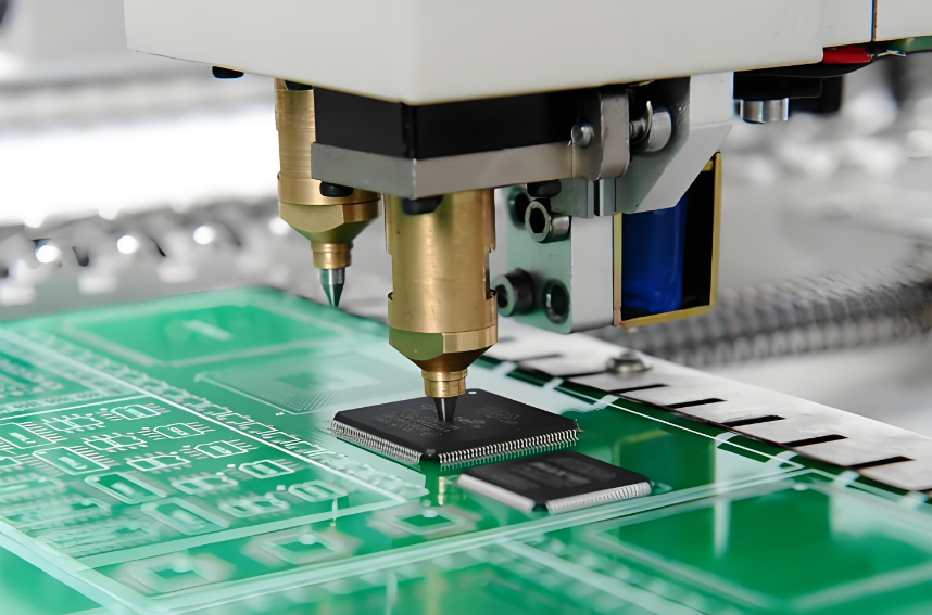
4. Component Placement
After printing, components are placed onto the board using high-speed pick-and-place machines, and precise alignment is required to ensure proper contact with solder pads. Since flex PCBs are supported by carriers, placement accuracy depends heavily on fixture stability.
In addition, lightweight handling and controlled machine settings help prevent shifting or misalignment during this stage.
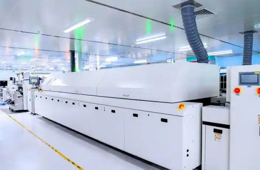
5. Reflow Soldering
The assembled board then enters the reflow oven, where the solder paste melts and forms electrical connections between components and pads. However, the temperature profile must be carefully optimized, because excessive heat or rapid temperature change can cause warping or damage.
Important control points include:
- Gradual heating and cooling rates
- Uniform temperature distribution
- Controlled peak temperature based on material limits
This step is critical, as improper reflow can lead to solder defects or mechanical stress.
6. Cleaning (If Required)
After reflow, flux residues may be removed depending on the application requirements, especially in high-reliability or high-frequency products. Cleaning methods must be compatible with flexible materials to avoid damage or chemical residue.
At the same time, low-residue or no-clean flux is often preferred to simplify the process.
7. Inspection and Quality Control
Once assembly is complete, the boards undergo multiple inspection stages to ensure quality and reliability. These inspections help detect defects early and maintain production consistency.
Typical inspection methods include:
- AOI (Automated Optical Inspection)
- X-ray inspection for hidden joints
- Visual inspection for mechanical defects
By combining different inspection techniques, manufacturers can ensure both solder quality and structural integrity.
8. Functional Testing and Final Verification
Finally, the assembled flex PCB is tested to verify electrical performance and functionality, ensuring that it meets design specifications. Functional testing may include signal integrity checks, continuity testing, and system-level validation.
At this stage, only fully qualified boards proceed to packaging and shipment.
9. Packaging and Handling
The last step involves proper packaging to protect the flexible boards during transportation, and special care is taken to avoid bending or mechanical stress. Anti-static packaging and customized trays are often used to maintain product integrity.
Overall, the flex PCB assembly process is a combination of precision engineering and careful handling, where each step directly impacts final product quality. By controlling materials, fixtures, and thermal profiles, manufacturers can achieve stable yield and reliable performance in flexible electronics.
Flex vs. Rigid-Flex PCB: Which One Fits Your Application?
Flex and rigid-flex PCBs serve different purposes, and selecting the right type depends on mechanical and electrical requirements.
| Feature | Flex PCB | Rigid-Flex PCB |
| Structure | Fully flexible | Combination of rigid and flex |
| Cost | Lower | Higher |
| Mechanical strength | Moderate | High |
| Design complexity | Simpler | More complex |
| Application | Wearables, compact devices | Aerospace, medical, automotive |
Flex PCBs are suitable for lightweight and simple structures, while rigid-flex PCBs provide better mechanical support and integration in complex systems.
How to Ensure Signal Integrity in High-Speed Flexible Circuits?
Maintaining signal integrity in flexible circuits is essential, especially in high-speed PCB or RF applications. Since flex materials behave differently from FR-4, careful design is required to minimize signal loss.
Important considerations include:
- Controlled impedance routing
- Proper grounding and shielding design
- Short and direct signal paths
- Selection of low-loss dielectric materials
In addition, consistent manufacturing quality also plays a key role, because variations in trace geometry or material properties can affect signal performance.
Which Flexible Substrates Offer the Best Reliability?
Material selection directly affects the reliability and performance of flex PCB assembly, so choosing the right substrate is critical for long-term stability.
Common materials include:
- Polyimide (PI): high thermal stability and flexibility
- Polyester (PET): lower cost but limited heat resistance
- Liquid Crystal Polymer (LCP): excellent high-frequency performance
Among these, polyimide is the most widely used due to its balance of flexibility, durability, and thermal resistance.
How Does Stiffener Placement Affect Assembly Durability?
Stiffeners are often added to flex PCBs to improve mechanical strength and support component areas, and their placement plays an important role in assembly reliability.
Key considerations include:
- Place stiffeners under connectors or heavy components
- Avoid stiffener edges in bending areas
- Ensure proper bonding between stiffener and substrate
- Select suitable materials such as FR-4 or polyimide
Proper stiffener design helps prevent mechanical stress concentration and improves overall durability during both assembly and operation.
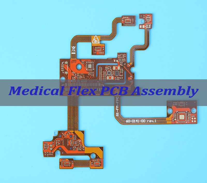
Which Industries Use Flex PCB Assembly the Most?
Flex PCB assembly is widely used across industries that require compact design and high reliability, especially where space and weight are critical factors.
Major applications include:
- Consumer electronics (smartphones, wearables)
- Medical devices (imaging systems, portable equipment)
- Automotive electronics (sensors, control modules)
- Aerospace and defense systems
- Industrial automation and robotics
As electronic devices continue to become smaller and more complex, the demand for flex PCB assembly continues to grow.
FAQs about Flex PCB Assembly
1. How do I prevent “Solder Bridging” on flexible circuits?
Use precision-cut stencils and high-tack solder paste. Because flex boards can expand slightly during heating, we use specialized vacuum fixtures to keep the substrate perfectly flat during the printing and placement process.
2. Can Flex PCBs handle high-current applications?
Yes, by increasing copper weight or using multi-layer flex constructions. However, this increases stiffness, so a balance between current capacity and bend radius must be calculated during the design phase.
3. What is the minimum bend radius for a Flex PCB?
Typically, for a single-layer flex, the bend radius should be at least 6x the thickness. For multi-layer or flex PCB assembly with components, the radius should be significantly larger to avoid trace delamination.
4. Why is “Baking” necessary before assembly?
Flex materials are hygroscopic (they absorb moisture). We bake all flexible circuits before reflow to prevent “popcorning” or delamination caused by trapped moisture turning into steam at high temperatures.
5. What is the best way to attach a Flex PCB to a housing?
Pressure-sensitive adhesives (PSA) like 3M 467 are commonly used. These provide a strong bond while allowing the circuit to maintain its flexible properties without adding significant bulk.
6. How do you test Flex PCB reliability?
We perform “Mitigation Testing” and “Dynamic Flex Tests.” This involves mechanically bending the assembly for thousands of cycles while monitoring for changes in resistance or continuity.
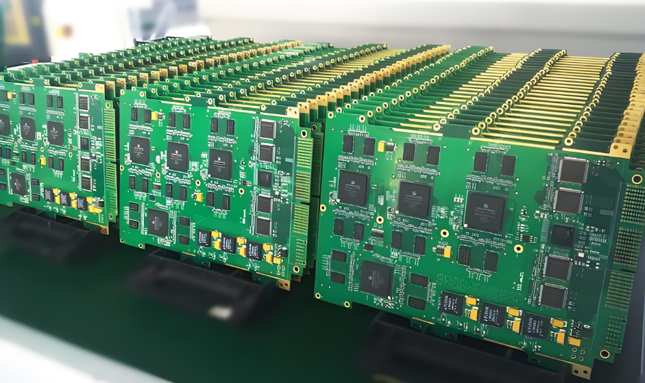
Get a Quote from EBest Today
At EBest, we specialize in high-precision flex PCB assembly for the most demanding industries. Whether you need a quick-turn prototype or full-scale production, our team is ready to deliver quality you can trust.
We provide premium flex PCB products tailored to your specific technical requirements. Ready to start your next project?
Contact us today: sales@bestpcbs.com
You may also like

Tags: china flex pcb assembly, Flex PCB Assembly, flex pcb assembly manufacturer, flex pcb assembly process, rigid flex pcb assembly