Best Technology Co.,Ltd
- +86-755-2909-1601
- sales@bestpcbs.com

Printed circuit board (PCB) design is based on circuit schematics to realize the functions required by the circuit designer. This is a complex process that includes several steps, such as schematic drawing, layout design, DFM and testing.
A good PCB design can create functional, reliable, and cost-effective circuit boards that meet the electrical and physical requirements of the devices they will be used in. PCB design is critical to ensuring the proper operation of devices and minimizing the risks of electrical shorts, interference, and other problems that can arise from poor design. PCBs are widely used in various electronic devices, from small consumer products to large industrial machines.


We uphold the following design principle: cost-effectiveness, security, compliance, performance,reliability and time to market.
Throughout the design process, we’ll collaborate with you on any required design changes and provide suggestions to improve your new product.
Full turnkey PCB design served for more than 1700 customers, include but are not limited to BYD, DIDI, HUAWEI.


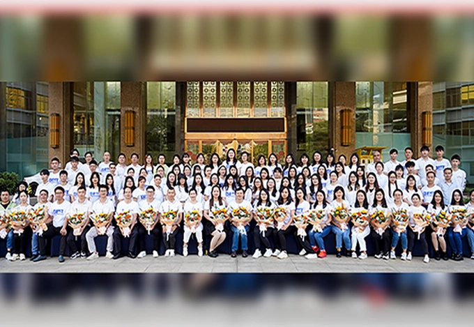
Best Technology is a well-known PCB manufacturer and PCB assembly for over 18 years. We offer full turnkey PCB design and PCB layout service. All you have to do is provide the idea, and we'll make it come true.
Our products ranging from standard FR4 PCB, multi-layer PCBs, metal-based PCBs (MCPCBs), ceramic PCBs, flexible and rigid-flexible PCBs to high frequency PCBs. Currently our mouthy capability is 260,000 square feet (28,900 square meter), more than 1,000 different boards will be completed. We also provide expediate service, so that urgent boards can be shipped out within 24 hours.
At a custom printed circuit board manufacturer, we believe that continuous growth is the key to success. So, we always invest much in research and development to stay ahead of industry trends. Our focus on product quality and customers satisfaction, and we aim to build strong relationships and offer personalized support and solutions to our customers.

Are you worry about quality certificates? No worry, we have relevant quality certifications and RoHS compliant quality management system to ensure good PCB quality.
To make sure the one-time success of the PCB design, we offer a full series of analysis such as PI, SI, EMC, DFM and so on. We have served more than 5000 PCB design cases for communications, serves, automotives, lightings.

We are committed to offering high-quality PCB solutions at competitive prices. By optimizing our production processes and managing costs efficiently, we ensure that you get the best value for your investment.

At Best Technology, quality is our top priority. We perform strict quality control procedures cover every stage of production, from raw material selection, prototyping to final product testing.

Our all-in-one approach simplifies supply chain, shorten lead times, and improves communication efficiency. And we have one-on-one sales-assistant service to give you a wonderful experience work with us.

We understand the importance of meeting your project deadlines, and we offer online WIP updates to make sure you can keep track of the progress of your PCB product.
Before your engineers design the PCB, you can communicate with us knowing that we are going to understand what it is you need, and that we can offer the best way to get them there. The follows basic three steps to design your circuit board .
Step 1 - Gather the necessary informations:
Request these guides before starting your design process:
Learn PCB General Design Tips, dimensional tolerances, conductor design data, and artwork layout, etc.
Get a brief glance at our production capability to get the design assistance and specifications for flex circuits.
Learn the information about material of PCB, Ceramic PCB substrate, and choose a suitable types. For example, if you want to have designed impendance control, you need to know material Dielectric constant of material (for FR4, the popular value is 3.8~4.8) . You can see our excel formal to calculate impedance, or use professional tool such as Polar Si6000b, Si8000m.
Step 2 - Choose a suitalbe PCB types and follow up standard design flow
If you'd like to use high density, need dozens of layers, then use multi-layer FR4 PCB; if want good heat elimination, then metal core PCB will be a good idea; if you need RF board, then consider using Rogers or Telfon; if you are going to solder ceramic Cap, ICs, Resistors on PCB and need a high precision on dimension, low expansion coefficient, high thermal conductivity and high-temperature resistance, excellent erosion and wear resistance, then Ceramic PCB will be best choice.
you want to design Metal Core PCB, you should know T-Guard for performance by Best PCB, they have excellent design guide for MCPCB, from single layer to double layers, through Multi-layers MCPCB. You can also download it here:
T-guide for Performance
T-guide for Manufacturability
Single Layer IMpcb Fabrication Guideline
Multi Layer IMpcb Fabrication Guideline
For Ceramic PCB design, please see following design guide.
DCB Ceramic PCB Design Guide
Thick Film Ceramic PCB Design Guide
Step 3 - Send us your request for quote:
Our policy is to identify and correct potential problems with flexible circuitry at the quoting stage, not after we accept your order. We can use any information you have and create a fully functional board for you. We can accept various file formats with our state-of-the-art CAM software. Using our experience and knowledge of flex printed circuits, We can go through your supplied files and spot any potential design problems before they get to photo production. We can edit your files to make sure they are per DFM (Design for Manufacturability). Best FPC can also use a supplied schematic and design you a custom FPC from that!
To evaluate your circuit board and quote a firm price we need:
A circuit drawing with outline dimensions, cutouts, and dimensional tolerances.
A Drill Chart of hole locations, sizes, and access hole diameters with tolerances.
A material cross section (circuit stackup) specifying thickness of each layer.
A photocopy of artwork or CAD data (if available) showing conductor layout and widths, with all applicable tolerances.
All testing, inspection, and packaging requirements.
A "Readme" file in txt or PDF.
Because its special characteristics of thick film ceramic PCB, you cannot design that ceramic board following the design rule of FR4. Here are simple design guide for Thick Film Ceramic printed circuit board.
A) About Ceramic PCB Substrate / Raw Material
Substrate/Core raw material type: Alumina (96% Al2O3), BeO, AIN;
Substrate/Core raw material Thickness: 0.25mm, 0.38mm, 0.50mm, 0.63mm(standard), 0.76mm, 1.0mm, and 1.27mm (only for AIN), and special thickness such as 1.6mm, 2.0mmm, need to be customized.
B) Conductor (metallization), Trace Layer
Conductor (metallization) material: Silver Palladium (AgPd), Gold Palladium (AuPd), and Mo/Mu+Nickel plating (for Ozone)
Application type: SMD/SMT; Aluminum-Wire Bonding; Gold-wire bonding, Ozone plate. Please advise that information so that different material and thickness will be adopted accordingly
Conductor (metallization) layer thickness: >=10um
Minimum (Min) Trace Space/Width for volume production:0.30mm & 0.30mm, 0.20mm/0.20mm is also okay but cost will be higher, and 0.15mm/0.20mm only available for prototype.
Layers Number: 1L, 2L, Double sided (with PTH), 3L~10L with or without PTH
C) Conductor Resistivity
Different conductor material has different resistivity value.
The thicker conductor thickness is, the lower resistivity value will be.
Some famous & popular material value:
Dupont 6177T (AgPd): <=18mOhm/square @ thickness 15um;
Dupont 6179 (AgPd): 12~15mOhm/square @ thickness 12~15um;
Dupont 5771 (AuPd): <=7.0mOhm/square @ thickness 6-9um;
ESL 9562 (AgPd): 6mOhm/square @ thickness 12.5um;
ESL 9562-G (AgPd): <=4mOhm/square @ thickness 12.5um;
DHC-PF-8083D (AgPd): <=10mOhm/square @ thickness 10-15um;
D) Conductor Power Density
The power density for conductor itself should be limited to max 600 Watt/inch2 of conductor surface. And power density for an Al2O3 substrate should be limited to 8 Watts/in2 (for the total of all conductors on top of it)
If you have a Ag conductor line of 0.3inch long, 0.010 inch wide (=30 square (0.3/0.01)), the surface area is 0.3 x 0.01 = 0.003 in2. This means the carrying powder P is limited to 600 (power density) x 0.003 (area) = 1.8 watts.
Assume conductor resistivity is 6mOhm/sq/12.5um (ESL9562), the resistance value R = 30 sq x 6mOhm = 0.18 ohm.
Power = I2 x R, or I2 =Power/R=1.8/0.18 = 10, so the carrying current limit I = 3.16 amps. Or in a short equation: I (amps) = line width (inch) x (power density)1/2 / (sheet resistance, ohm) 1/2
If the trace keep 0.3 inch long, but change width to 0.02inch, (=15 square (0.3/0.02), the surface area is 0.3 x 0.02 = 0.006 in2. This means the carrying powder P is limited to 600 (power density) x 0.006 (area) = 3.6 watts.
And resistance value for that trace will be 15 square x 6mOhm = 0.09 ohm, and then 3.6/0.09= 40, I=6.325 amps.
If the trace width keep 0.01inch, but change line to 0.6 inch long (=60 square (0.6/0.01), the surface area is 0.6 x 0.01 = 0.006 in2. This means the carrying powder P is the same as 3.6 watts. (600x0.006).
But the resistance value for that trace will change to be 60 square x 6mOhm = 0.36 ohm, and then 3.6/0.36= 10, I=3.16 amps. So you can see, it’s no useful to change the trace line.
So if you want to have bigger current, then you need to increase the width of trace.
E) Surface finishing:
For conductor is AgPd or AuPd, then surface finishing is raw material itself, no extra finishing. For Mo/Mu, then Nickel plating.
F) Bonded Resistors:
Different resistor value can be put on the same board, each different resistor period need to set up a new stencil, and can only be printed separately.
Resistor can be on the same layer/side, or different layer/side
Bonded resistor can support high temperature up to 500C;
Please advise temperature coefficient
G) Soldermask
It is glass glaze
Ceramic PCB can be either with or without soldermask
Color: transparent greenish
H) PTH (Plated Through Hole) & NPTH (Non-Plated Through Hole)
Both are available
Min NPTH: 0.10mm
Min PTH: 0.15mm
Maximum (Max): No limited
There’s a special layer up for ceramic PCB more than 1L. See “Ceramic PCB Layer up_BestTech” , or See “Ceramic PCB Layer up_BestTech.pdf” separately.
I)Manufacturing Tolerance:
Board Thickness: +/-10%, Min: +/-0.08mm
Outline to Outline: +0.20mm/-0.05mm
NPTH: +/-0.05mm
PTH: +/-0.10mm
NPTH to NPTH: +/-0.05mm
PTH to PTH: +/-0.10mm
NPTH to edge: +0.15mm/0.05mm
PTH to edge: +0.20mm/0.10mm
J) Panel & Shipment:
Max panel size: Normal size 138*80mm, and maximum size 200x200mm. Special size also available
If board shape is square, rectangle, it can be shipped via both panel and single piece; otherwise, has to be shipped via single piece
X-Out board should be allowed for panel delivery
K) Lead Time & Cost
Prototype: 2.5-4 weeks
Volume production: 3.5-5 weeks for initial order, 2-3 weeks for repeated order, or 1-2 weeks if give us forecast.
Following elements will increased the cost:
More hole (PTH or NPTH)
Gold Palladium (AuPd) used
Different resistor value on same board
Big size
Big hole
PTH expensive than NPTH
0.635mm raw material thickness is the cheapest
Because its special characteristics of DCB ceramic board, you cannot design DCB PCB following normal FR4 PCB design rule. Here are simple design guide for DCB ceramic printed circuit board.
Conductor material: Copper, thickness 0.1mm~0.3mm;
Copper thickness VS trace space & trace width
For 0.1mm (3OZ) copper thickness, trace space & width should be 0.3mm;
0.2mm copper, 0.4mm space & width;
0.3mm copper, 0.5mm space & width
Maximum effective working area: 126x176mm
Substrate (Al2O3 & AIN) thickness:
0.25mm (seldom used, extreme expensive), 0.38mm, 0.50mm, 0.63mm(standard), 0.76mm, 1.0mm, and 1.27mm (only for AIN)
There should be 0.3mm margin between trace and edge of board at each side for 0.1mm thickness copper; 0.4mm margin for 0.2mm copper thickness; 0.5mm margin for 0.3mm copper thickness;
Surface finishing: Nickel (1~7um); or Aug plating (0.075~0.1um, 3~4 u”)
No soldermask is better (working temperature is -55~+850C, as most of ceramic board was working in high temperature > 200C, no good oil is suitable for that temperature range)
We will ship via single piece, as Al2O3 need to be cut by laser and not easy de-panel like normal FR4 PCB
ore hole, more expensive. Min hole: 0.15mm, no Max. Hole diameter > 0.5mm will be better in price.
Normally trace should be related much simple compared with FR4 board
Knowing ceramic substrate feature will be better for you to understand and design a good board. Here is a picture showing above design guide.
Simply drop your email or phone number in the contact form, and we'll promptly provide you with a quotation.